| john@email.johncon.com |
| http://www.johncon.com/john/ |
|
|
|
||
Using the Maxim/Dallas Semiconductor DS18S20 as a Temperature Sensor |
|||
Home | John | Connie | Publications | Software | Correspondence | NtropiX | NdustriX | NformatiX | NdeX | Thanks
|
The Maxim/Dallas DS18S20 1-Wire Parasite-Power Digital Thermometer and DS9097U Universal 1-Wire COM Port Adapter can be used to sense temperature for home heating-ventilation-air-conditioning, (HVAC,) cost optimization as part of a home automation, (HA,) project. The cost savings can be substantial-reductions of a factor of 2 being typical in the temperate zones. The DS18S20 sensors and DS9097U serial port adaptor are readily available can be ordered from Maxim/Dallas or Digi-Key, and the sensors are cost less than US $3.00 each in single units. Maxim/Dallas supplies an SDK, (software developer's kit; for development of commercial programs, check the license information in Maxim/Dallas' uLinuxGNU310r2.zip SDK archive,) of C sources for the DS18S20/DS9097U which can be linked into a program, simplifying development-which is used by the temp.tar.gz program sources archive, (see tempS0 for the man(1) page for the program.) The Maxim/Dallas uLinuxGNU310r2.zip SDK archive is included in the temp.tar.gz program sources, which has a shell script to extract the necessary driver source files for compilation of the tempS0 program. The network requirements for a home-wide HA/HVAC precision control system are straight forward, and can be constructed out of simple CAT3, (i.e., standard telco wiring-although routing cables will probably be required and it is almost as cost effective to run CAT5/CAT5e shielded cabling, for future use; it is the construction standard in the US today.) A word of caution on using telco extension cords-they are not network compatible, and almost always have one of the RJ11 plug upside down, (i.e., there is a twist in the cable that is undesirable for network cabling.) It is probably best to use bulk, (i.e., 100' spools,) of cable, cut to custom length, and assemble the RJ11 plugs on each end with a crimper, (inexpensive plastic crimpers are available for RJ11 for under US $10.) Note that the plugs should be the same on both ends of the cable: after the plugs are assembled on each end, look at the ends of both plugs with the metal toward you, and with the tab on the top of both; the color of the wires should be black-red-green-yellow, from your left, to your right, on both plugs. It is acceptable to intermix 4 wire and 6 wire plugs on 4 wire or 6 wire cables; if 4 wire cable is used with 6 wire plugs, make sure the 4 wires are in the center 4 connectors of the 6 wire plug, (and in the correct order-starting with black, on the left, ending with yellow, on the right.) Although CAT5/CAT5e shielded jacks can be used, (and are recommended,) there is a substantial cost savings when using CAT3 jacks, (and they work fine for 1 wire networks,) when routing through walls, into the attic through the ceiling, etc. The wiring from jack to jack should follow the color code on the jacks, and be straight through, (i.e., no color swapping.) Inexpensive plastic push down tools for installing the cables on the jacks are available for under US $10, and many of the jacks come with an installation tool. If reliability is an issue, the jacks should be installed in walls in an electrical utility/junction box available at any home improvement store in the electrical department-many stores also carry CAT3/CAT5/CAT5e components, complete with faceplates, etc. 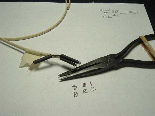 Figure I. DS18S20 Being Soldered to CAT3 CableFigure I shows the Maxim/Dallas DS18S20 being soldered to CAT3 Cable. For parasitic operation, (i.e., the power for the DS18S20 taken from the clock line, with no external power supply,) pins 1 and 3 of the TO-92 should be shorted together, and connected to ground. Although this can be done at the TO-92 package, I ran the shorting wire down, from pin 1, and up, to pin 3, and striped back one wire in the CAT3 for power-for future use. The long nose pliers are used as a heat sink, and stabilize the TO-92 package during soldering. 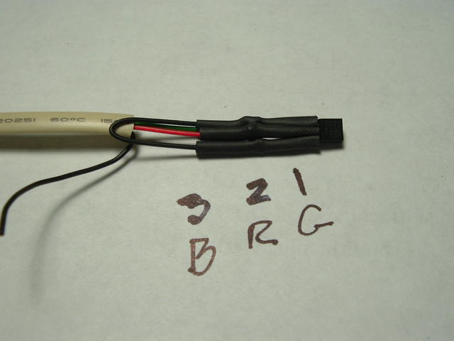 Figure II. DS18S20 Temperature Sensor and CAT3 Cable ConnectionFigure II shows the Maxim/Dallas DS18S20 temperature sensor and CAT3 Cable Connection. The heat shrink tubing was purchased at Radio Shack, and was shrunk using a common hair dryer. 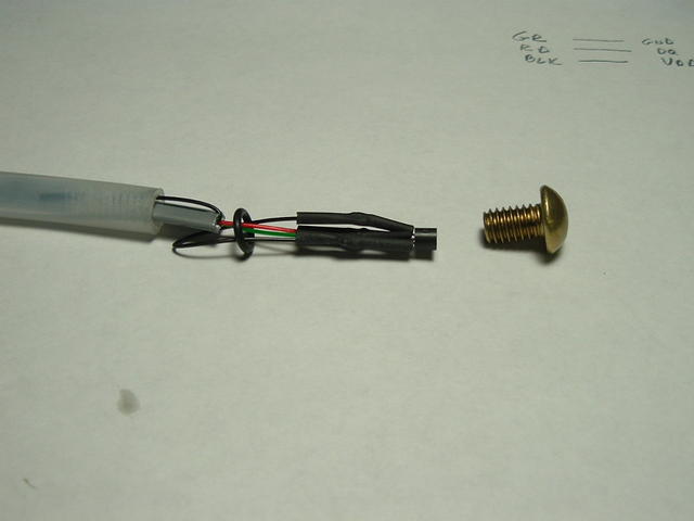 Figure III. Assembly of the DS18S20 ThermometerFigure III shows the assembly of the Maxim/Dallas DS18S20. The 5/16-18 X 1/2 brass machine screw was purchased at the local home improvement store, and will be screwed into the thermometer housing with heat sink compound applied between the screw and the DS18S20. The O ring is a #5 O-Ring, 3/8" O.D. X 1/4" I.D. X 1/16", (Danco part number #96722,) and is for faucet repair from the plumbing department at the local home improvement store-it will provide a water tight seal between the thermometer housing and brass screw. The brass screw and O-ring cost under a dollar, US. The thermometer housing is about a half foot length of 3/8 X 1/4 polypropylene tubing commonly used for hooking up water to a refrigerator ice machine-and was purchased in a 25' length from a local home improvement store. The edge that contacts the brass screw should be a straight as possible-it will form the water tight seal with the O-Ring and brass screw. The thermometer housing will be affixed to a wall, etc., with the brass screw sticking out into the room about 1" to measure the room temperature. A 5/16 - 18 tap was used to make the threads in the polypropylene for the brass screw. The tap and tool cost under US $5, each, in the tool department of any local home improvement store. The heat sink compound used between the screw and DS18S20 is available from Radio Shack, and US $5 will buy more than will ever be used. The thermal conductivity of brass is 109, and polyethylene HD is 0.42-0.51, (see: Thermal Conductivity of some common Materials,) meaning that the brass screw is located in ambient air, and reasonably well thermally insulated from the wall-so the ambient air temperature is measured, (by the sensor which is in thermal contact with the brass screw,) and not the temperature of the wall. After assembly, the sensor is removed, (by pulling on the CAT3,) and the tip of the thermometer placed in a tall glass of water, overnight, to verify water tightness-the sensor reassembled, (by pushing on the CAT3,) and the other end of the polyethylene/CAT3 sealed with silicon cement to provide mechanical integrity for the CAT3 cable. The thermometer's total bill-of-materials is under US $5, each, and take about 15 minutes to solder the cable, and assemble. For internal thermometers, (mounted in the wall, through a 3/8" hole,) the thermometers are painted with with matching wall paint. For external thermometers, they are painted flat white, (titanium oxide-which is used on radar towers-is best, but was not available, so inexpensive flat white spray paint was used,) and placed in a small tilted box, (made out of scrap lumber,) open at the bottom and front, (for adequate air circulation, and shielding from rain-so it will measure air temperature, and not rain temperature,) which is painted flat white, also. For external units, see PWS - Siting for siting issues. Outside thermometers should be mounted in an eternally shaded area, 5' above ground, (that's the standard.) To find sun angles, see: Time and Date for the angle of the sun at the two annual solstices for siting the location. 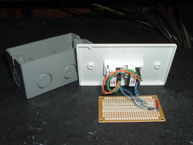 Figure IV. Construction of the DS9097U/DS2480B RC-FilterFigure IV shows the construction of the DS9097U/DS2480B RC-Filter, as recommended in Maxim/Dallas application note AN148, Appendix D, for networks less than 200 meters in total length. The box is an inexpensive utility/junction box available in the electrical department of any home improvement store. The PC board is Radio Shack part number 276-150, and wedges securely into the utility box. The components are a 1/4 Watt 100 Ohm resistor and a 4700 pF capacitor-these are common values, inexpensive, and if you don't have them, they are available from Digi-Key or Allied Electronics for under a dollar US. Only one is required for the entire network.
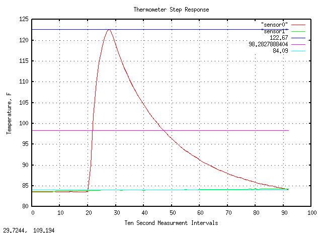
Figure V. Thermal Step Response of the DS18S20 ThermometerFigure V is a plot of the step thermal step response of the DS18S20 thermometer. For the task at hand, (room/outside ambient temperature measurement,) sampling a network of thermometers every 6 minutes = 0.1 hour would be adequate, and making the time constant somewhat less than that would provide adequate thermal filtering. The measurement was made by filling a cup with hot tap water, (about 155 F,) placing the thermometer in the hot water, and when the temperature reaches 125 F, removing, (and quickly drying,) the thermometer, allowing it to cool down in ambient air. The time constant measures 3 minutes, 11 seconds, meaning the measurement interval is about twice the time constant of the thermometer. (The program used to interrogate the thermometer sensor was temp from the DS18S20 SDK.)
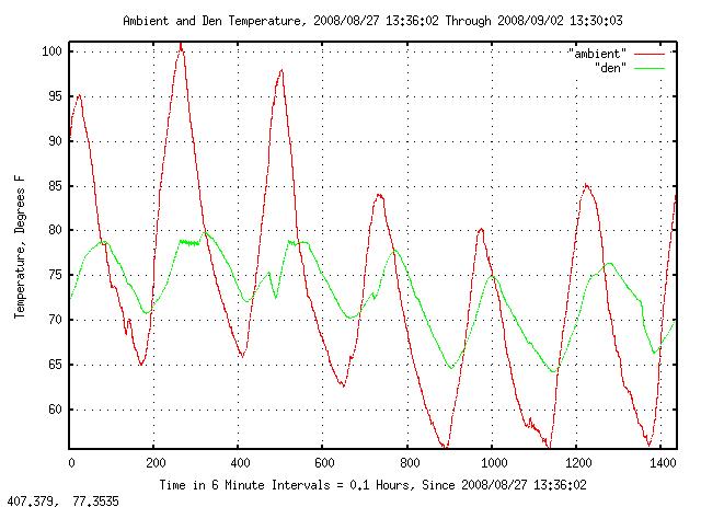
Figure VI. Some Experiments with DS18S20 Based ThermometersFigure VI is a plot of some experiments with DS18S20 based thermometers. The ambient temperature is outside temperature, and is compared with the den, inside temperature. The air conditioner cycling on/off at time mark 300 can clearly be seen, (it comes on 1/4 degree above the thermostat setting, pulls down to 1/4 degree below the setting, and goes off.) The Weather Underground forecast for the next day was about the same, so a manual pull down was initiated at time mark 500 to verify that time-of-day pricing structures could be optimally addressed by pulling down the temperature in early morning, (when electricity is less expensive,) to accommodate high afternoon temperatures, (when pricing is more expensive.) During the evening interval around time mark 1000, the windows in the house were opened to pull down temperatures overnight, and compared with the next day, where they were not opened until around time mark 1350 to compare the slopes of the temperature ramp down. Conclusion: opening/closing the windows when the outside and inside temperatures cross can be an effective cost control strategy for HVAC, (at least at 37N, -122W.) I use this method by having the system send a text message when the two temperatures cross. The glitch in inside temperature at about time mark 700 was intentionally created by manually turning the air conditioning on to measure the interaction between the air conditioning exhaust and the outside thermometer-they are about 20' apart-and the exhaust created about a 0.5 F error after running 18 minutes, (it can be seen in the outside temperature at that time,) which is deemed to be acceptable. Although elegant mathematical models exist for HVAC control, most do not fit easily into economic models using tiered or time-of-day electricity pricing structures. However, modeling the house in terms of thermal conductivity can be used for straight forward cost optimization. The thermal pole of the house in Figure VI is about 3.5 days, (which fits conveniently into the thermal management mathematical infrastructure used in the electronics industry.)
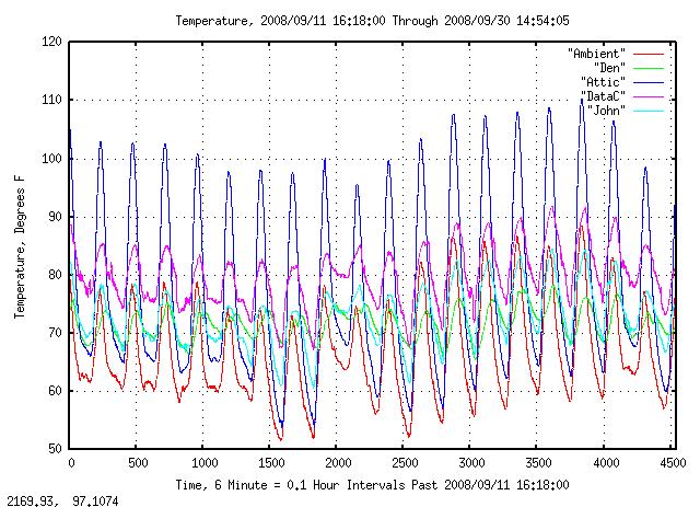
Figure VII. Network of DS18S20 ThermometersFigure VII is a plot of a network of DS18S20 thermometers. Again, the ambient graph is outside, and the graph is for 19 continuous days. The temperature of various rooms was added, including the attic, to evaluate how effective the insulation is. Note that this is a reasonable compromise-lowering the attic temperature (via convection or circulation,) to save air conditioning money in the summer may be offset by the decrease in heating by sunlight in the winter, raising heating costs later in the year. Such optimizations do not lend well to analytical solutions, and require long term temperature measurement and analysis. As a closing note, the financial time series analysis programs at the NdustriX site work well for thermal analysis, too, and are compatible with the temp.tar.gz programs, like the logs/database made by the tempS0 program. About This ProjectThis project began in the summer of 1974-I am a semiconductor engineer, and had moved from Texas Instruments, in the Dallas metropolitan area to Motorola Semiconductor, (now Freescale Semiconductor,) in the Phoenix, Arizona, metropolitan area. With daytime maximums exceeding 120 F, and nighttime minimums as high as 110 F, in the summer, energy management is a significant issue. I used several bipolar transistors in a TO-92 package for the temperature sensor, that run at 1 mA quiescent current, pulsed instantaneously to 10 mA, (quite precise, using a current mirror, and diff-pair current pulse steering/control,) and measured the Vbe delta of the transistor with a dual slope, (ramp up under 1 mA, ramp down under 10 mA,) analog to digital, (A/D,) converter, (using a single op-amp, and C-MOS switch to zero the charge across the integration capacitor, and a TTL counter,) which-in theory-would have a linear temperature dependence on the delta Vbe. The control/data processing was done in a 6800 evaluation board, (using Mike-Bug, as the development system,) by shoving the A/D counter output on the machine's external hardware CPU stack. The algorithm formed a lead compensation, (similar to the anticipator used in current industrial building environments,) between the outside and inside temperatures, and worked quite well, giving an energy cost reduction of about a factor of 1/2. In 1976, I left Motorola Semiconductor for Fairchild Semiconductor in Mountain View, California, and the project was abandoned-until the energy cost spikes of 2000, when the project was re-developed using modern temperature sensors, and a PC running Linux, which is what this page is about. The initial analysis yielded some interesting insight:
There are other options, too-like using multiple PC fans, (27 CFM each, for the 80 mm fans,) operated through relays, (or solid state relays,) off of a PC power supply, (the fans and supply are typically 100,000 hours MTBF of operation, and are reversible,) in each exiting duct vent at the room interface, (as opposed to a central fan unit,) to provide the forced air for the HVAC. This would provide a means to force air from cooler, (perhaps non-occupied,) rooms to warmer rooms-like the upstairs in a two story house, without using the AC. Its too early to tell, (it will require several years of data,) but there is a good possibility that the 68/78 specification can be met in the summer by opening/closing the windows, (when the inside/outside temperature differential = 0,) and no AC, whatsoever. It is a very extensible system, and is very inexpensive, (it currently runs in a 14 year old 90 MHz. Pentium class machine-that was salvaged-with 16 MB of memory.) As a budgetary, the sensor's total cost, (including cabling, tools, etc.,) averages about US $10, per sensor, for a typical house-which has a relatively quick ROI-and about 30 minutes total assembling time, (including the thermometer and routing the cabling, etc.) LicenseA license is hereby granted to reproduce this design for personal, non-commercial use. THIS DESIGN IS PROVIDED "AS IS". THE AUTHOR PROVIDES NO WARRANTIES WHATSOEVER, EXPRESSED OR IMPLIED, INCLUDING WARRANTIES OF MERCHANTABILITY, TITLE, OR FITNESS FOR ANY PARTICULAR PURPOSE. THE AUTHOR DOES NOT WARRANT THAT USE OF THIS DESIGN DOES NOT INFRINGE THE INTELLECTUAL PROPERTY RIGHTS OF ANY THIRD PARTY IN ANY COUNTRY. So there. Copyright © 1992-2008, John Conover, All Rights Reserved. Comments and/or problem reports should be addressed to:
|
Home | John | Connie | Publications | Software | Correspondence | NtropiX | NdustriX | NformatiX | NdeX | Thanks