| john@email.johncon.com |
| http://www.johncon.com/john/ |
|
|
|
||
EWE Shortwave Antenna |
|||
Home | John | Connie | Publications | Software | Correspondence | NtropiX | NdustriX | NformatiX | NdeX | Thanks
|
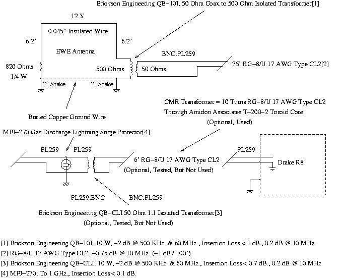
The EWE Antenna was first described by Floyd Koontz in QST Volume 79, 1995, (a reprint of original is available at http://www.ok1rr.com/view.php?cisloclanku=2004122603). Since the antenna has a useful bandwidth of about 2:1, and the short wave bands center around 10 MHz., 10 MHz. would be a reasonable design criteria. 10 MHz. has a wavelength of 100'; the antenna should be 1 / 4 wave length long, 1 / 8 wave length on the top, and 1 / 16 wave length on both sides, or 12.5' on the top, and 6.25' on the sides. The feed point impedance should be about 500 Ohms, and the termination resistance slightly less than twice the feed point impedance. An 820 Ohm metal film/low noise resistor was used for the termination. The antenna is directional (receiving radio waves passing from the termination end, to the feed end,) at lower frequencies in its bandwidth, omnidirectional at higher frequencies, and becoming directional in the opposite direction at frequencies much higher than the design criteria. Notice how small the antenna is, 12.5' x 6.25', which is adequate for a general purpose, or portable antenna-and works well as an internal antenna. 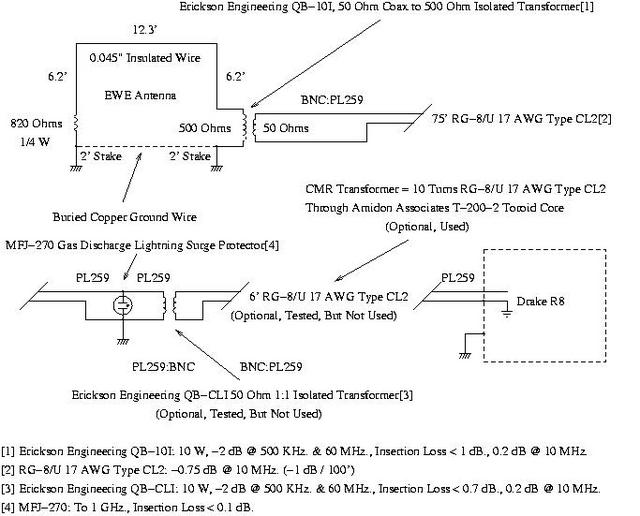 Figure I. EWE Shortwave AntennaFigure I, (which is available in larger size jpeg, or xfig, formats,) shows the attention to detail on the antenna lead in, impedance matching, etc. The antenna, (in the upper left of the diagram,) has two 2' copper rods, (purchased from the local home improvement center-they are about a quarter inch in diameter, but any metal rods will work,) driven in the ground 12.3' apart. These rods are connected by a buried bare copper cable, (I used antenna wire, but any copper cable-like stripped lamp cord-will work.) There have been reports that the EWE antenna is sensitive to ground resistivity, and this technique was considered advisable. Each ground rod has a water proof electrical utility box, (available from the local home improvement store,) mounted at ground level, with one containing the 50:500 Ohm balun, the other contains the 820 Ohm termination resistor. The antenna wire runs from the top of the balun up, (for 6.2', across for 12.3', and down 6.2' to the termination resistor. The antenna's listening direction is from the balun to the termination resistor, (i.e., the antenna receives signals from the left, to the right, in Figure I.) A word about antenna lead in:
Note that these are general considerations for getting the antenna signal to the receiver, while limiting stray pickup of RFI, etc. A General Discussion of Short Wave AntennasMany designers will use design equations for transmitting antennas for receiving antennas, and then via reciprocity arguments, optimize the receiving antenna. However, it is more complicated for receiving antennas. Specifically because of atmospheric noise considerations.
At 10 MHz., the atmospheric noise will be about 2 uV, (daytime.) Now, assume the characteristics of a good receiver. From "R8 Communications Receiver: Owner's Manual," pp 4, 5.0-30 MHz, (preamp on,) the AM sensitivity for 10 dB S + N / N, 1000 Hz., 30% modulation,) is less than 0.8 uV. 10 dB is a ratio of 3.1623, or the noise floor would be (0.8 uV + N / N) = 3.1623, or N = 0.37 uV. Note that the atmospheric noise is 5 times as large as the receiver noise-which is the rule-of-thumb for receiver designers-if the noise level jumps when the antenna is plugged in, the antenna is working fine, (this comparison should be made with a dummy load vs. the antenna-but just plugging in the antenna and looking for an increase in noise is a good reference.) As a tutorial example, suppose a signal level is equal to the atmospheric noise level, and suppose the antenna has a gain of 0.2, (-14 dB,) then the noise level increased by 3 dB, (remember noise adds root-mean-square, and the antenna noise and receiver noise are equal in this example,) so the signal is -3 dB below the noise at the receiver output. Note what happened: the antenna gain was -14 dB, which decreased the signal level, relative to the noise level, by only -3 dB at the receiver output. The EWE antenna gains run about -14 dB, typically, meaning if lead in losses, impedance matching, stray noise pick up, etc., are well managed, the antenna can exhibit good receiving characteristics. PerformanceOn 1200-0800 GMT, inclusive, on June 12 thru June 15, 2007, the r8.tar.gz program for controlling the R. L. Drake R8 Communications Receiver via an RS232C serial port, (see: r8.txt for particulars,) was used to scan the frequencies listed in http://www.primetimeshortwave.com/, (from http://www.n3kl.org/sun/noaa.html, the Solar X-rays were Normal, and, Geomagnetic Field was Quiet.) The results for world-wide English transmissions were:
Of those English language broadcasts logged, 43 were from ROW, (Rest of world,) directed to North America, 41 were directed from ROW to ROW. (Broadcasts originating in North America were omitted from the search.) The EWE antenna was located at Lat: 37 deg., Lon: 121, aligned 29 degrees East of True North. ComparisonThe EWE antenna was compared with an "A-B" switch with the Terminated Tilted Folded Dipole Shortwave Antenna, and compared favorably. The T2fd averaged about 4 dB lower noise figure than the EWE antenna across 5.75 MHz. to 18 MHz. The EWE was usable down to 3 MHz., the T2fd was not. The T2fd had better man-made noise, (i.e., local CRT RFI, etc.,) performance, (but that's the T2fd's forte.) Note that the T2fd's performance was slightly, (4 dB,) better, but when ease of maintenance and construction are considered, its doubtful that the T2fd is worth the additional effort, (the EWE is totally in reach while standing on the ground.) In an informal comparison, the EWE was compared against a random long wire, (10' off the ground, 40' long, jury rigged,) running through a 50:500 Ohm balun, and the signal to noise ratio was slightly better with the EWE. Additionally, the EWE was slightly better with local RFI pickup, (but not as good as the T2fd.) LicenseA license is hereby granted to reproduce this design for personal, non-commercial use. THIS DESIGN IS PROVIDED "AS IS". THE AUTHOR PROVIDES NO WARRANTIES WHATSOEVER, EXPRESSED OR IMPLIED, INCLUDING WARRANTIES OF MERCHANTABILITY, TITLE, OR FITNESS FOR ANY PARTICULAR PURPOSE. THE AUTHOR DOES NOT WARRANT THAT USE OF THIS DESIGN DOES NOT INFRINGE THE INTELLECTUAL PROPERTY RIGHTS OF ANY THIRD PARTY IN ANY COUNTRY. So there. Copyright © 1992-2008, John Conover, All Rights Reserved. Comments and/or problem reports should be addressed to:
|
Home | John | Connie | Publications | Software | Correspondence | NtropiX | NdustriX | NformatiX | NdeX | Thanks