| john@email.johncon.com |
| http://www.johncon.com/john/ |
|
|
|
||
Terminated Tilted Folded Dipole Shortwave Antenna |
|||
Home | John | Connie | Publications | Software | Correspondence | NtropiX | NdustriX | NformatiX | NdeX | Thanks
|
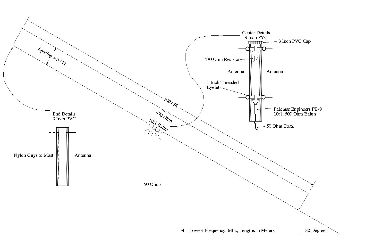
If you are a news junkie, and prefer getting your news directly from the source via shortwave radio, an antenna with excellent broadband performance is shown in Figure I, (which is available in larger size jpeg, PostScript, PDF, or xfig, formats.) The T2FD antenna is recommended for use in metropolitan areas, and the performance characteristics do not degrade in close proximity to metal objects, (like rain gutters,) foliage, etc. The antenna has omnidirectional gain characteristics and the performance is commensurate with a dipole, but has better man-made noise performance, and extremely wide bandwidth, (typically, 5:1.) 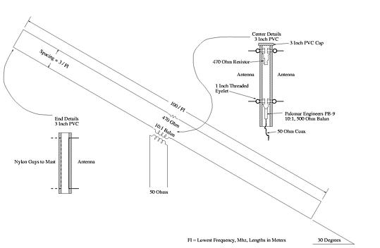 Figure I. Terminated Tilted Folded Dipole Shortwave AntennaMy own construction has a length of 48.25 feet, (limited by available space,) a width of 16.99 inches, and a tilt of 25.8 degrees, giving a lower frequency cutoff of 6.95 MHz. The antenna assembly is elevated 6 feet above the ground. The antenna has quite acceptable reception performance over the complete range of 5.0 MHz. to 30 MHz., (and is tilted directly over a 2 story house with of rain gutters on both stories-running inches from one-and is surrounded by foliage.) Both masts, (not shown,) were constructed from 3 inch PVC pipe, (as were both ends and center containers of the antenna,) one anchored to a second story chimney, the other to a fence post at ground level, (elevating the antenna 2 feet above the top of the fence, and 2 feet above the top of the chimney.) I used 25 pound test nylon for the guys at each end of the antenna for 50 pound safety shear failure, (in case weather brings the antenna down, the nylon will shear, preventing damage to the fence, chimney, and masts.) PVC glue was used to seal the center container against weather. Four standard 1 inch OD threaded eyelets were used for antenna wire attachments to the center container, with retaining nuts on the inside of the container-the antenna wire fastened directly to the eyelets, and a separate wire soldered to each antenna wire which connected to the resistor and balun mounted internally in the center container. The center container was supported by a two member vertical triangulated bracket made from 1.5 inch PVC pipe, and secured to the side of the house with two door hinges to permit lateral movement in strong weather. All hardware is readily available at a hardware store, and no special tools are required. A note about the balun: there are two types of baluns for matching a high impedance antenna, like the T2FD, to low impedance coax; transformer, (technically, a balun, balanced-to-unbalanced, which has a primary and secondary winding that are isolated,) and, auto-transformer, (technically, an unun, unbalanced-to-unbalanced, with a single winding that is tapped to provide the low impedance.) For a T2FD antenna, a balun is necessary, (and NOT an unun.) The noise performance of the balun is superior to the unun, since common mode noise, (for example, radiating from the high current magnetics driving a local television/computer CRT,) will tend to cancel since they are common to both legs of the T2FD. Additionally, it is advisable to insert a common mode choke in the lead in coax cable near the receiver-a common mode choke can be made by winding five to ten turns of the coax cable through a two inch toroid, (I use Amidon Associates T-200-2.) This attenuates common mode signals/noise picked up by the coax lead in. Also, its a good idea to use a common mode choke in the receiver power cord-made the same way; run about five to ten turns of the line cord through a two inch toroid. It is probably not practical to ground the coax lead in of a T2FD at the antenna, (this is the best way, and the coax should drop straight down to a grounding rod, the shield grounded, and then proceed on to the receiver, which is NOT grounded.) If the antenna is not grounded, then the coax shield should be grounded near the receiver, (i.e., the receiver ground should be connected to a ground rod-or as a less desirable alternative to the third/green wire of the power outlet.) The coax should not be grounded at both ends, (i.e., both at the antenna and the receiver.) For more details of good engineering practices for short wave antenna lead in, see EWE Shortwave Antenna. At the single ground point, (e.g., at the antenna or receiver,) it is always a good idea to install a lightning arrestor. I use the gas-discharge type. PerformanceThe antenna's performance was evaluated in an A-B comparison, (using a Drake R8, dipole cut for 9.545 MHz., broadside to Swiss Radio International from Northern California, W2AU Grove double to single ended balun.) Both antennas produced the same S unit response, (about S 9,) without preamplification. The RF gain was adjusted to S 1 on the dipole, and the antennas switched. The T2FD produced a S 1 reading. The receiver was tuned to a quiet location in the 9 MHz. band near 9.545 MHz., and the noise floor measured for both antennas, which were identical at 1.5 S units, (with preamplification.) The impedance of the T2FD antenna was measured, (through a connection of 5 feet of RG58 using a Palomar noise bridge,) at 0.25 MHz. intervals between 7 MHz. and 25 MHz., and found to exhibit an SWR of 1.5:1 over the range. The antenna's performance was then evaluated using the A-B comparison against the dipole at 1 MHz. intervals between 5 MHz. and 30 MHz., for both signal gain, and noise floor, and found to be as-good-or-better than the dipole in both S/N ratio and gain. HistoricalI have used the antenna since early 1990. It appeared in the "1989 Edition World Radio TV Handbook", (also called the WRTH,) Volume 43, 1989, Andrew G. Sennitt, Editor, Glenn Heffernan, Publisher, Billboard A.G., pp 566-567, "Equipment Test Bench Section," by Jonathan Marks and Willem Bos. Since anyone's chances of finding the reference is slim, the section is shamelessly plagiarized:
July, 2003 addendum: apparently, the original information on the T2FD antenna was described by Commander G.L. Countryman, W3HH, [QST, June 1949, pp. 54-55]. These antennas where used by the US Navy listening posts in the Pacific. Glenn Swanson, KB1GW, mentions in KB1GW's Collection of Beverage Antenna Information:
T2FD - The Forgotten Antenna has additional historical information on tests run by the US Navy in the late 1940's. T2FD LinksModeling the T2FDT2FD, The Forgotten Antenna -- antenna special on hard-core-dx.com UMB T2FD Antenna Receiving Balun from Wellbrook Communications RF Systems T2FD HF Aerials ttfd2-pt1 LicenseA license is hereby granted to reproduce this design for personal, non-commercial use. THIS DESIGN IS PROVIDED "AS IS". THE AUTHOR PROVIDES NO WARRANTIES WHATSOEVER, EXPRESSED OR IMPLIED, INCLUDING WARRANTIES OF MERCHANTABILITY, TITLE, OR FITNESS FOR ANY PARTICULAR PURPOSE. THE AUTHOR DOES NOT WARRANT THAT USE OF THIS DESIGN DOES NOT INFRINGE THE INTELLECTUAL PROPERTY RIGHTS OF ANY THIRD PARTY IN ANY COUNTRY. So there. Copyright © 1992-2008, John Conover, All Rights Reserved. Comments and/or problem reports should be addressed to:
|
Home | John | Connie | Publications | Software | Correspondence | NtropiX | NdustriX | NformatiX | NdeX | Thanks