| john@email.johncon.com |
| http://www.johncon.com/john/ |
|
|
|
||
Loudspeaker Design |
|||
Home | John | Connie | Publications | Software | Correspondence | NtropiX | NdustriX | NformatiX | NdeX | Thanks
|
The loudspeaker Thiele/Small parameters can be used with the Spice analog electronic circuit simulator to provide behavioral analysis of loudspeaker enclosures. Of particular interest is the frequency response, phase response, and group-delay of loudspeaker enclosures, each of which can be optimized for maximum performance. As an example, the Dayton Audio ND90-4 will be utilized in a design suitable for high quality computer monitors. The ND90-4 is rather unique in that the optimal, (optimized for low frequency response,) ported enclosure is nearly the same size as the optimal, (maximally flat midrange,) sealed enclosure, permitting an empirical comparison of the sound produced by both optimizations using the same enclosure for both. The ND90-4 driver is readily available, for under US $25, from Parts Express, Amazon, Ebay, etc. The DesigngEDA Electronic Design Automation tools, particularly, Gschem(1), was used for schematic capture and Spice electronic circuit simulation netlist extraction. Ngspice was used for the Spice circuit simulations The design work sheets and data bases for the speakers are available in a single tape archive format, (TAR file, using RCS for version control,) from nd90-4.tar.gz. Optimal DesignsThe optimization programs are avalable from the Subwoofer Speaker Design project as Calc(1) scripts:
The ported-box.calc
script indicates that a ported enclosure volume of 10 liters,
(which may be too large for most computer stations-the box
optimal internal dimensions are 13.7" X 8.5" X 5.2",) which
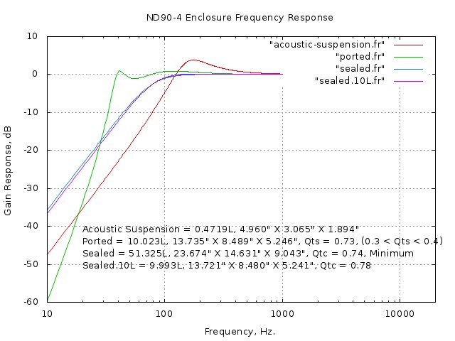
would have a low frequency -3 dB of 32 Hz., and the sealed-box.calc
script indicates that the 10 liter sealed enclosure would have
a low frequency -3 dB of 75 Hz., and a Q of 0.78, (a Q of
The Characteristics
Figure I shows the frequency response of the various optimal ported and sealed enclosure sizes utilizing the ND90-4 driver. Now that the optimal enclosures have been determined, the analysis can begin-remember, two designs, ported and sealed, are being developed. The Ported Design
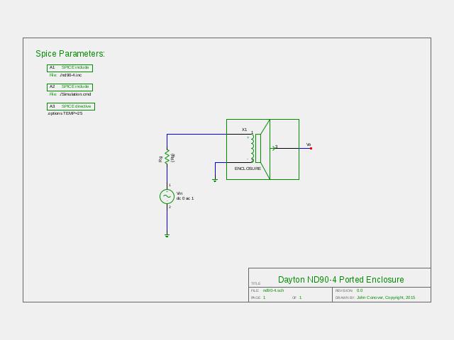
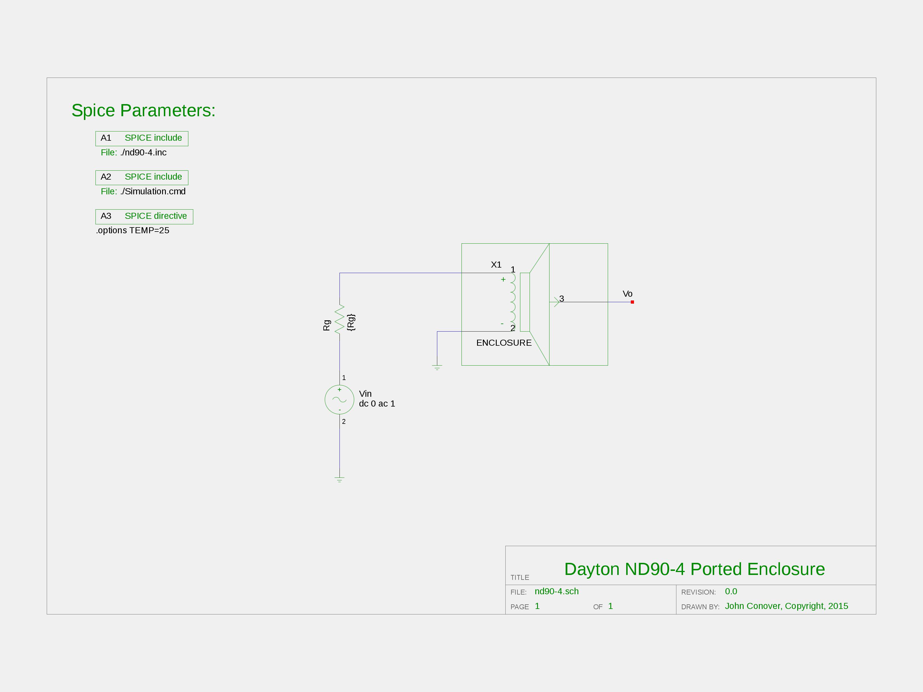
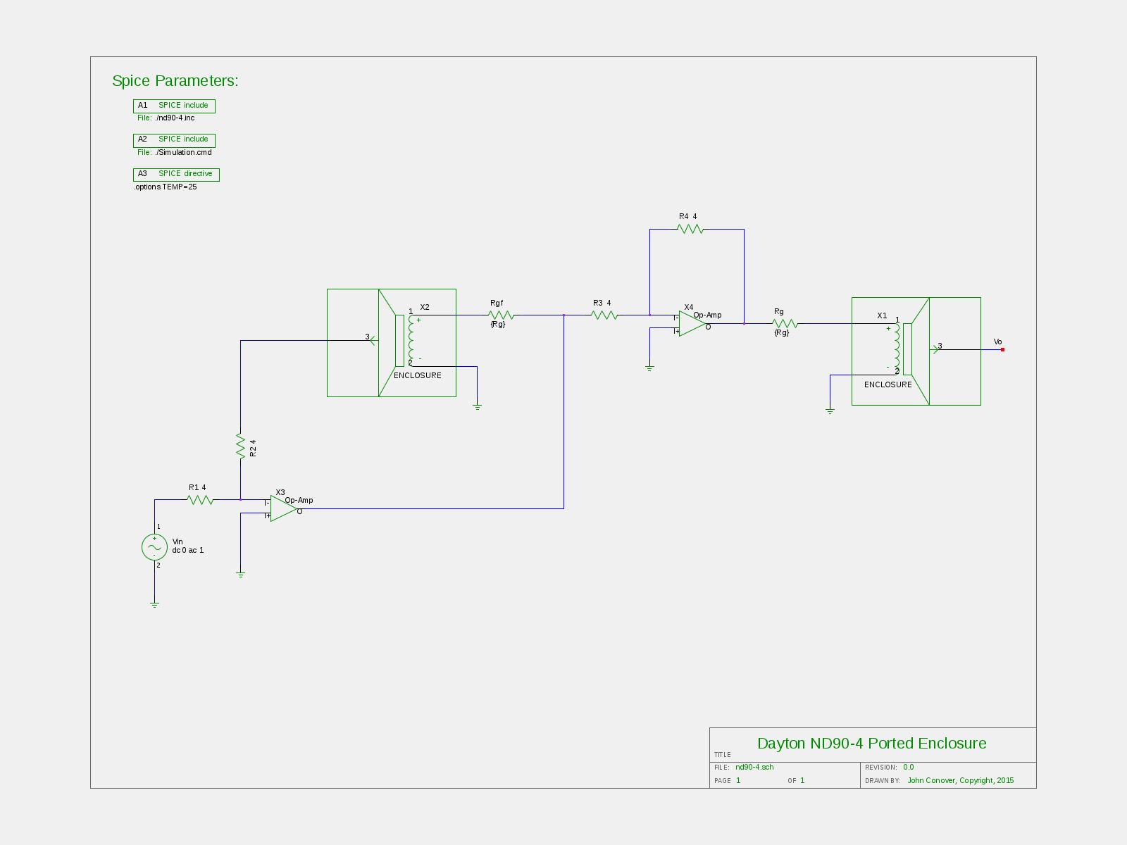
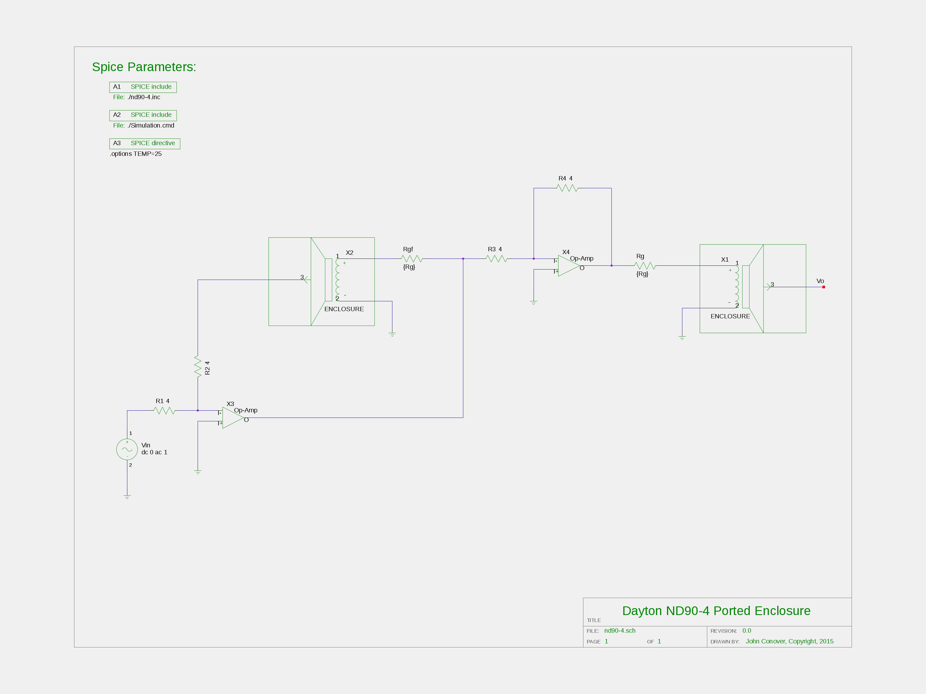
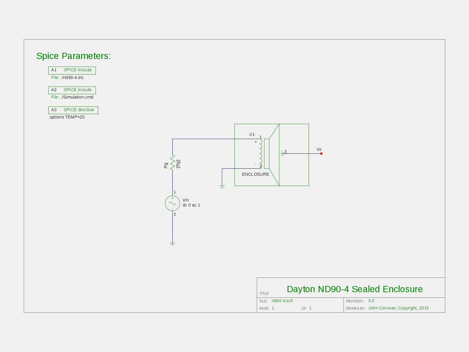
Figure II, (1600X1200),(3200X2400), is the ND90-4 symbol used for the ported design. And descending down the hierarchy of the ND90-4 symbol:
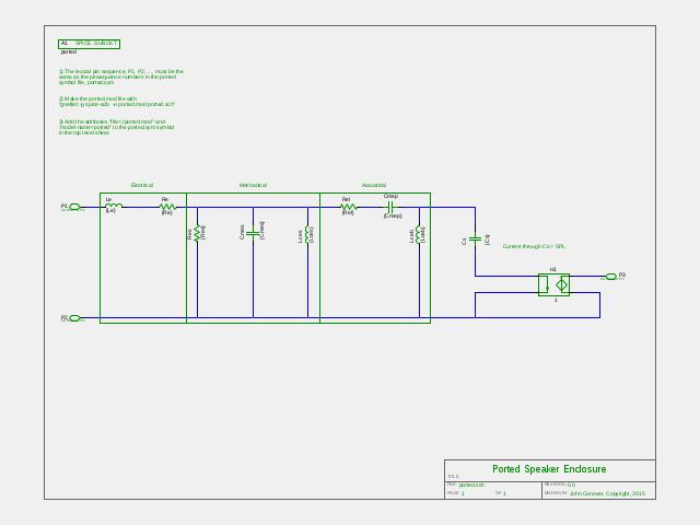
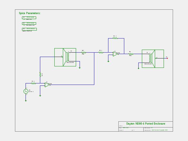
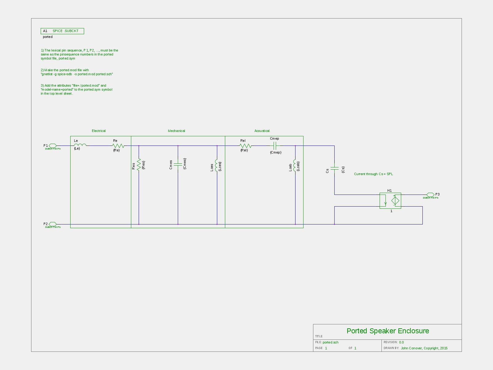
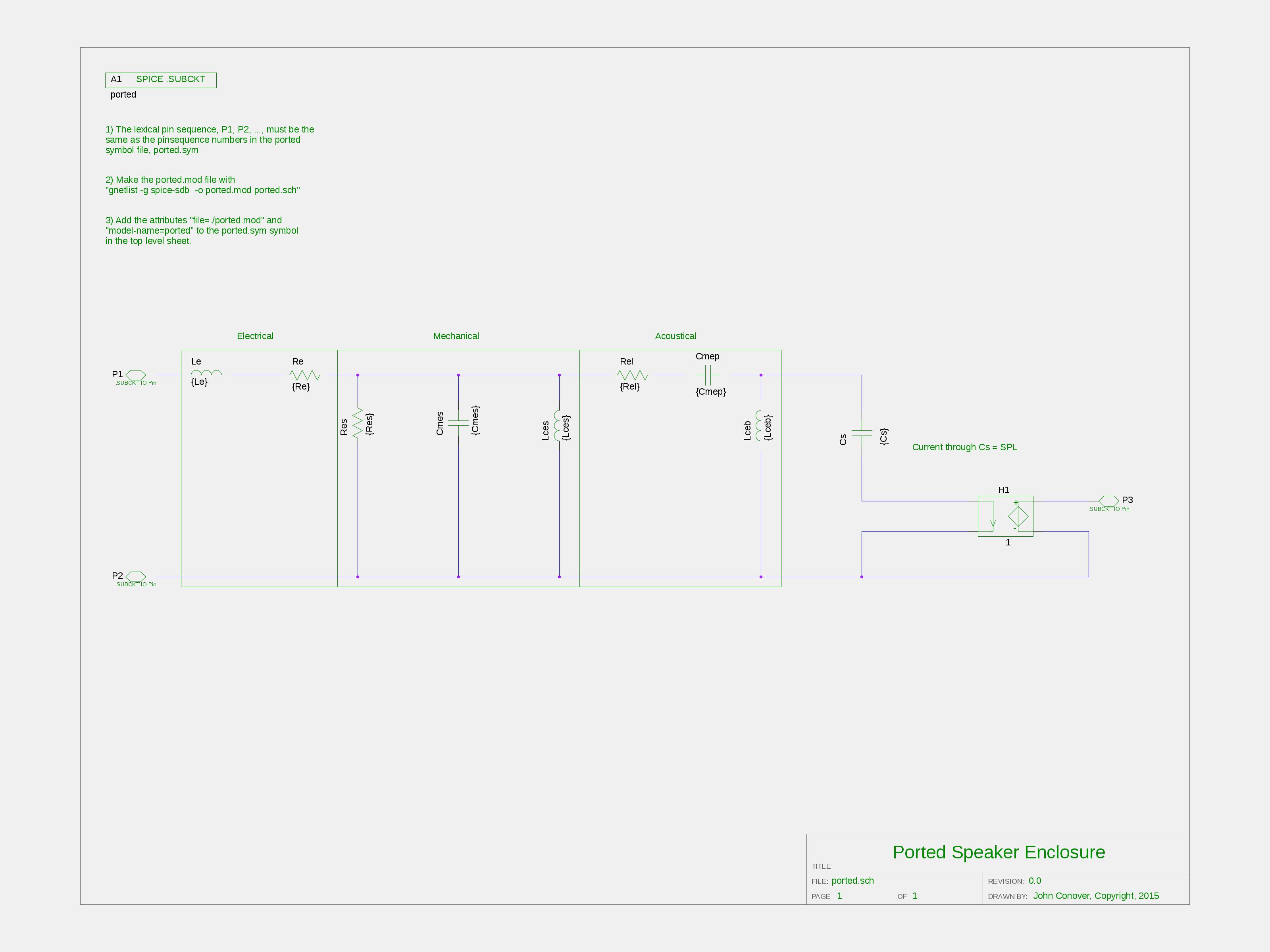
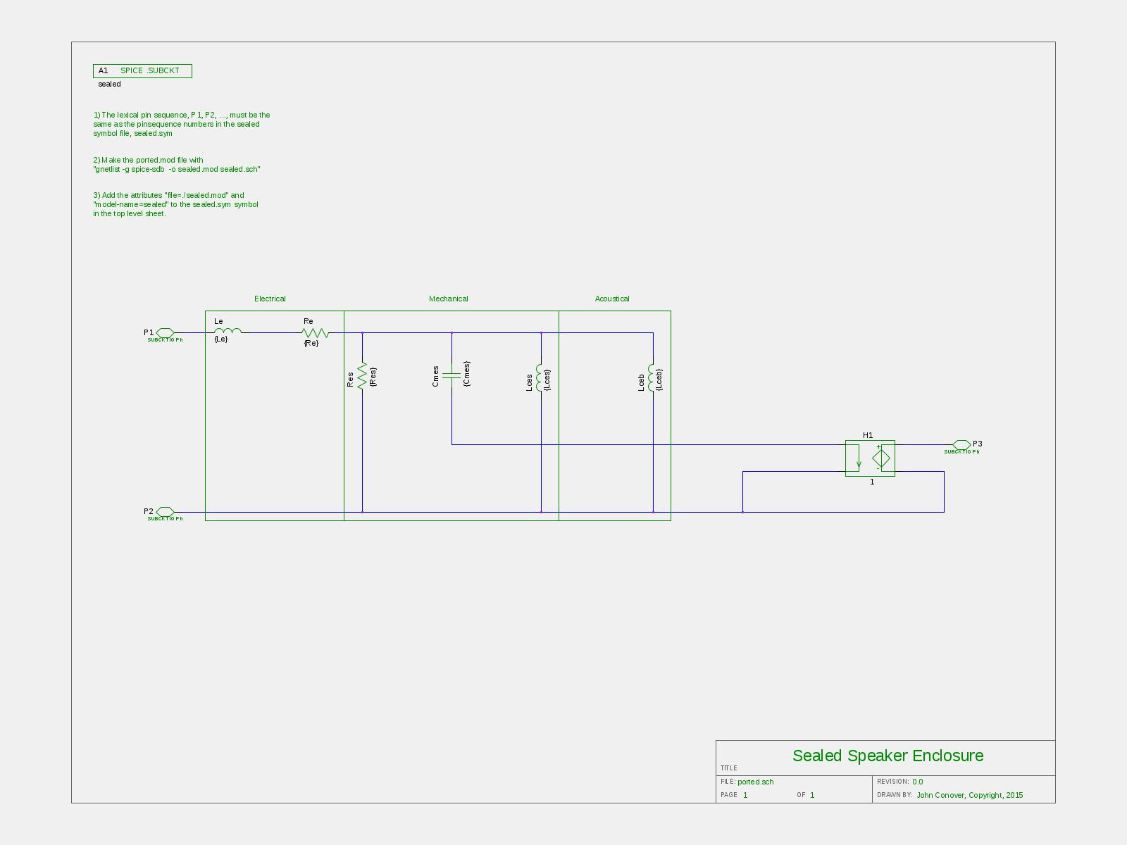
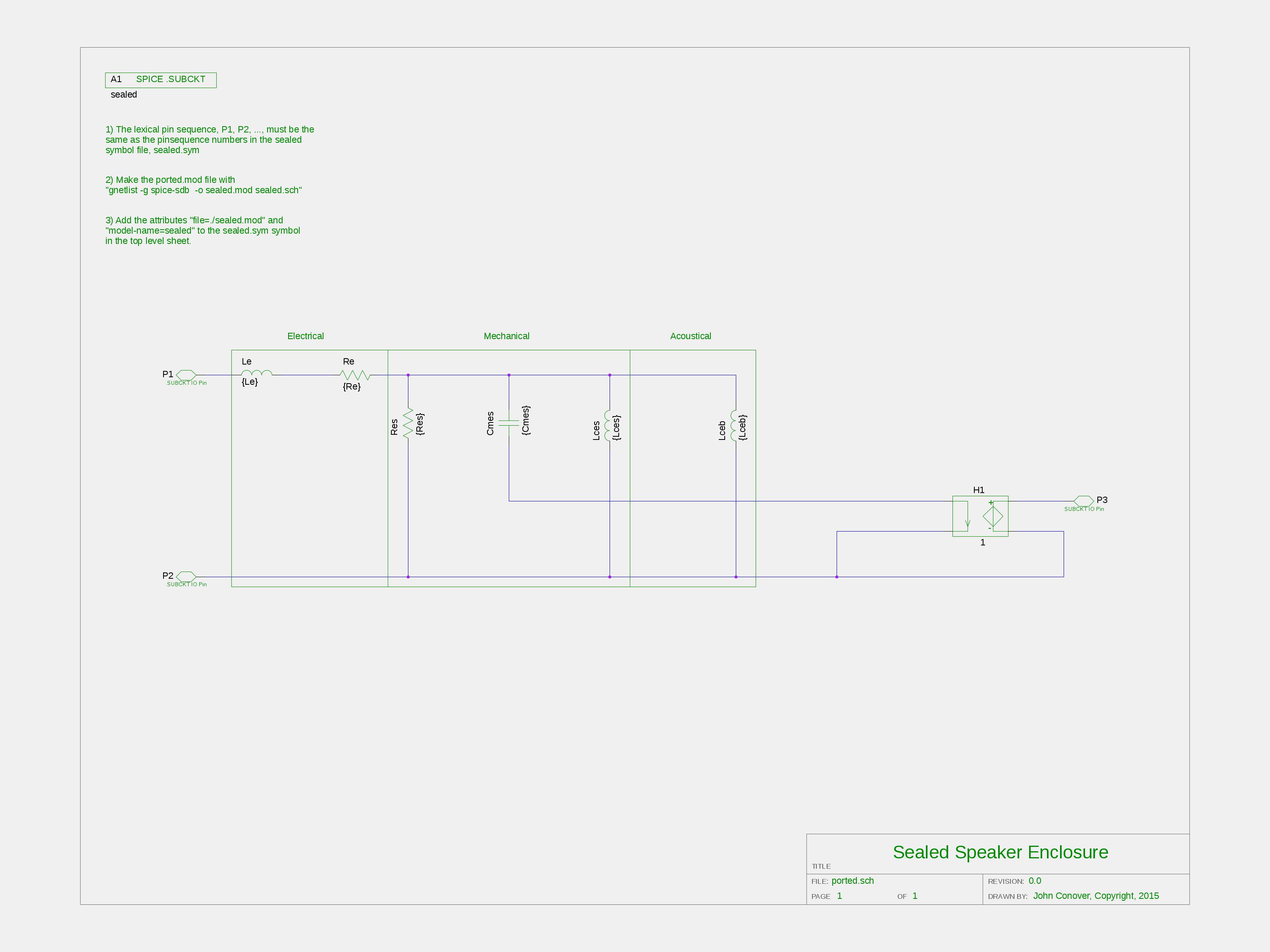
Figure III, (1600X1200),(3200X2400), is the schematic of the ND90-4 ported design using the Thiele/Small parameters.
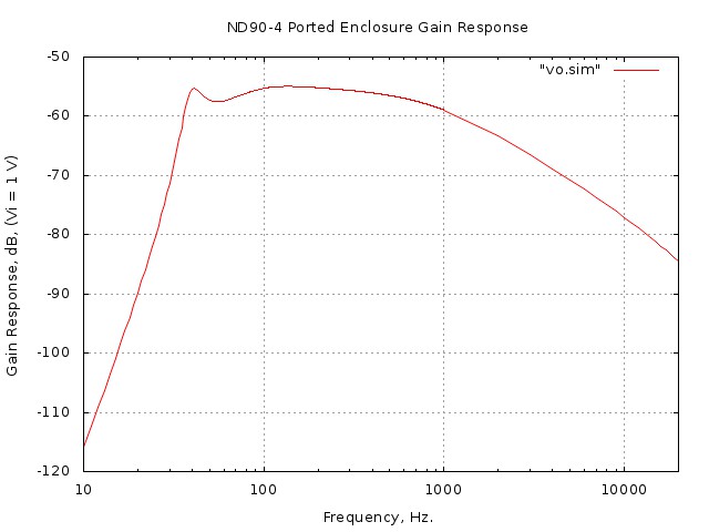
Figure IV is the frequency response, simulated using Spice, of the ported design.
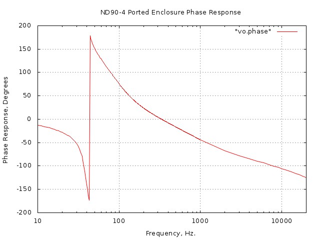
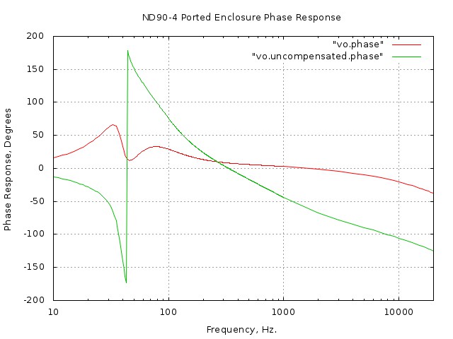
Figure V is the phase response, simulated using Spice, of the ported design.
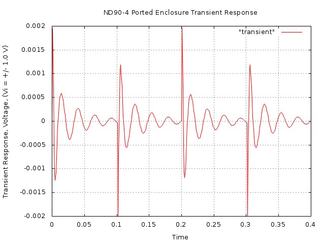
Figure VI is the transient response, simulated using Spice,
of the ported design. Note the ringing at the
enclosure's resonant frequency,
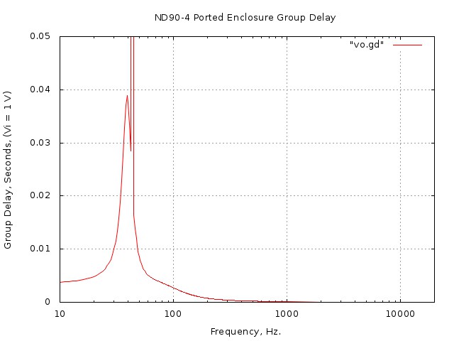
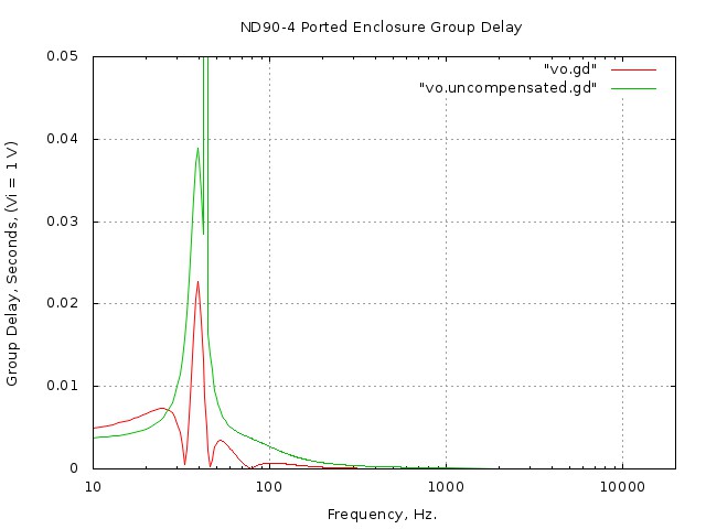
Figure VII is the group delay, simulated using Spice, of the ported design. Note that the group-delay of the ported design is acceptable, (at least by ported enclosure standards-but it is a controversial issue,) and is at the threshold of audibility. One of the advantages of using Spice simulations including the Thiele/Small parameters is the ability to electronically modify an enclosure's responses, (i.e., analog, DSP, etc.) For example, consider, (as a thought experiment,) using another ported ND90-4 driver's characteristics to modify the frequency response curves of the ND90-4.
Figure VIII, (1600X1200),(3200X2400), is the implementation of using a second ND90-4 driver to modify the frequency response curves of the ported ND90-4. Notice the subtle point: the second ND90-4,
Where
Figure IX is the frequency response using a second ND90-4
driver to modify the response curves of the ported
ND90-4. Note that the ouput of the
Figure X is the phase response using a second ND90-4 driver
to modify the response curves of the ported ND90-4. Note that
the output of the Note that this was a thought experiment, but we can approximate the response of the second ND90-4 with two all-pass filters to shift the phase of the ported ND90-4, addressing the issues of group delay.
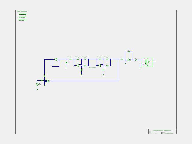
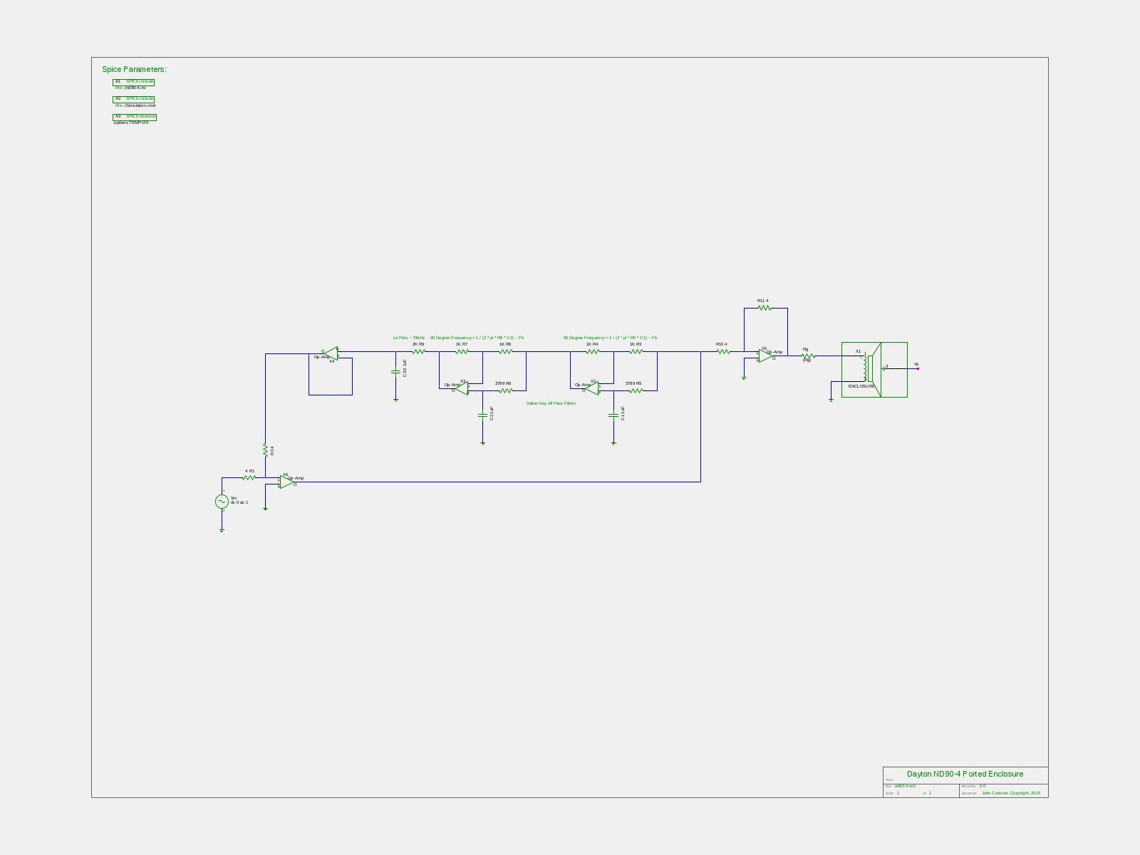
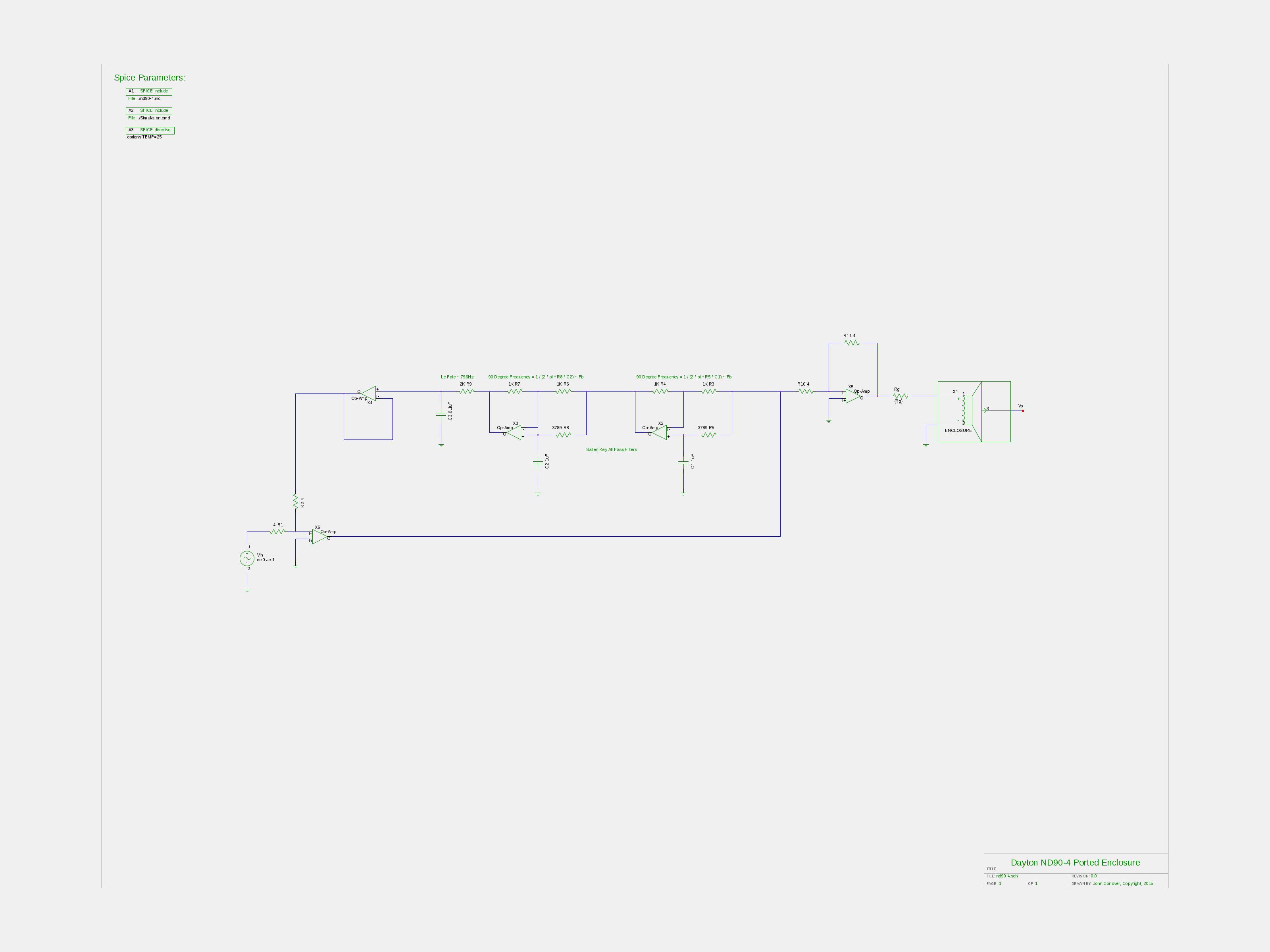
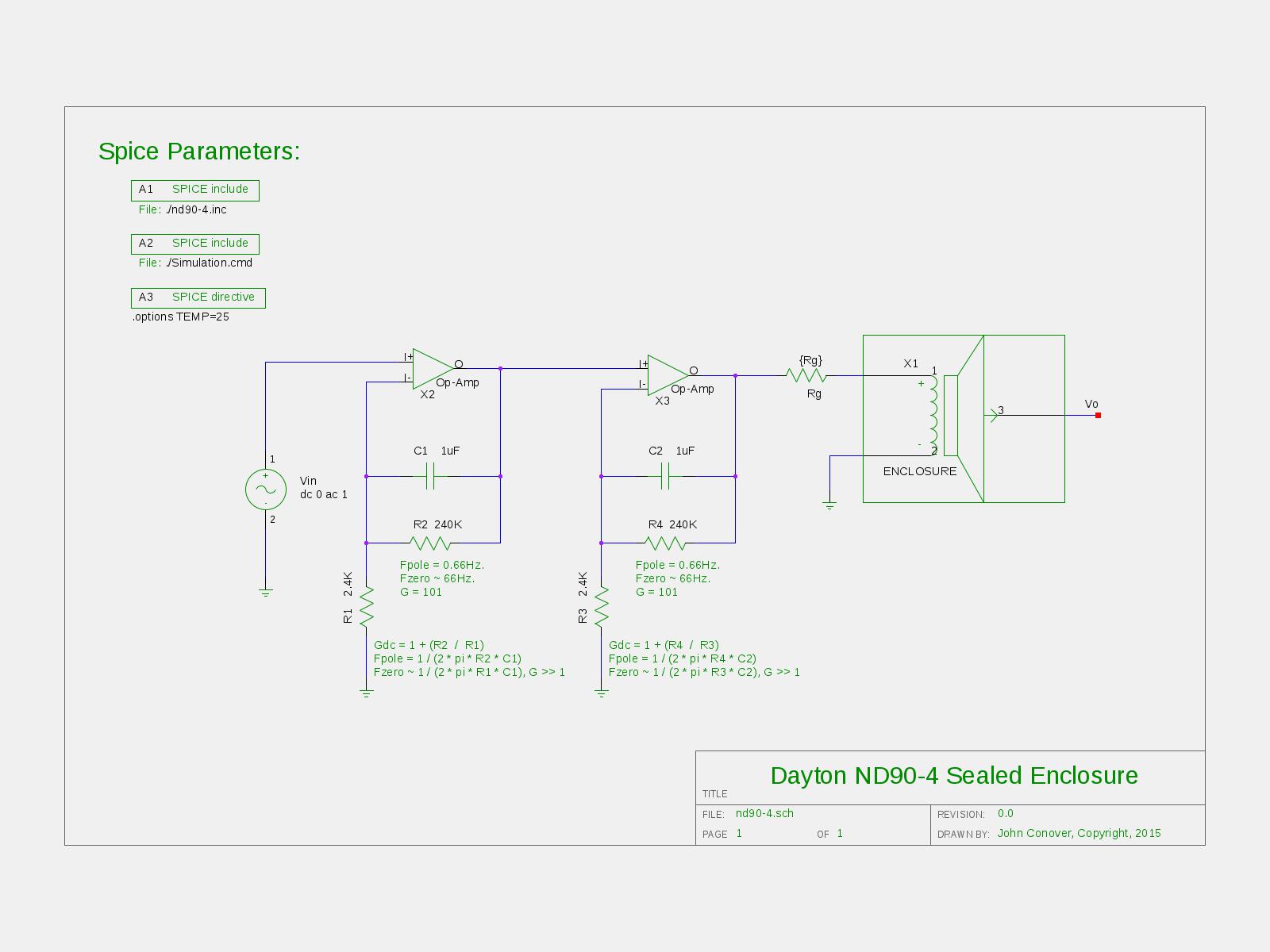
Figure XI, (1600X1200),(3200X2400), is the ported ND90-4 with two all-pass filters to shift the phase of the ported ND90-4, addressing the issues of group delay.
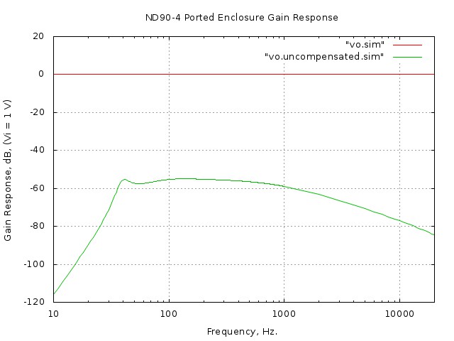
Figure XII is the frequency response of the ported ND90-4 design with two all-pass filters to shift the phase of the ported ND90-4, addressing the issues of group delay.
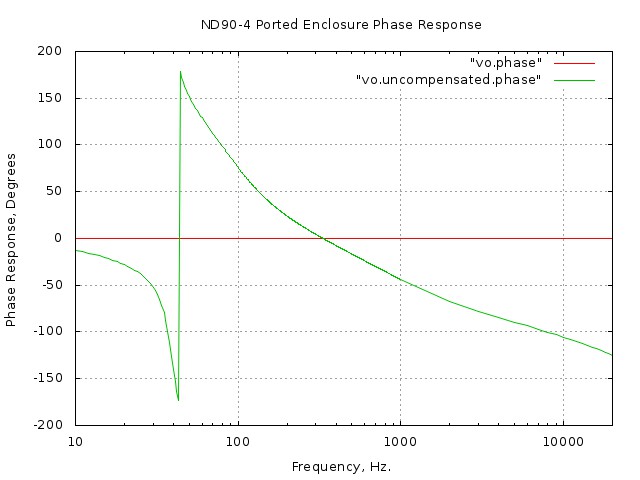
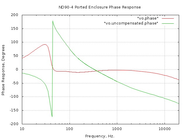
Figure XIII is the phase response of the ported ND90-4 design with two all-pass filters to shift the phase of the ported ND90-4, addressing the issues of group delay.
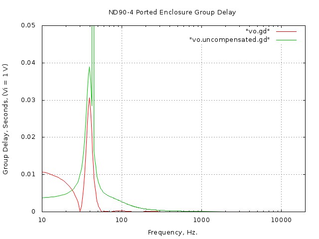
Figure XIV is the group delay of the ported ND90-4 design with two all-pass filters to shift the phase of the ported ND90-4, addressing the issues of group delay. Note that the all-pass filters are a simplified model of the ported ND90-4 and enclosure. A more complex model would use high-pass filters, with Q's
other than maximally flat, where
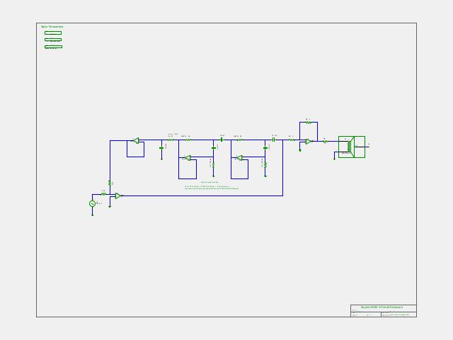
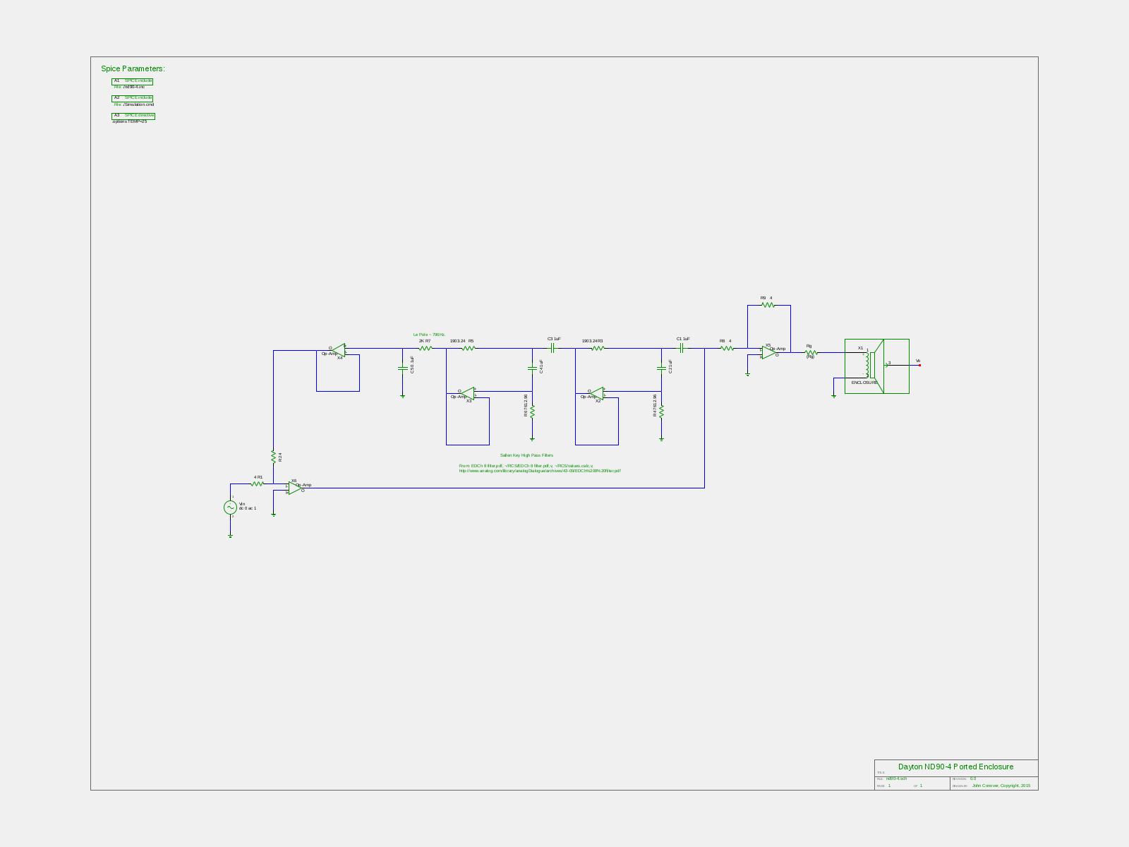
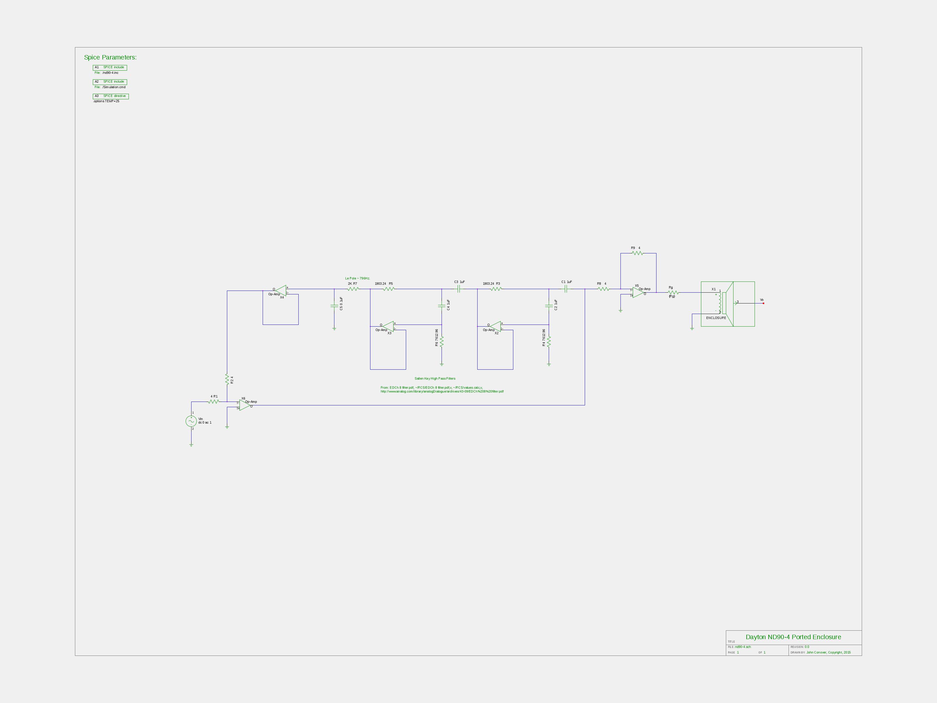
Figure XV, (1600X1200),(3200X2400), is the ported ND90-4 with two Sallen-Key high-pass filters to shift the phase of the ported ND90-4, addressing the issues of group delay.
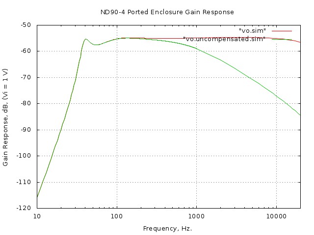
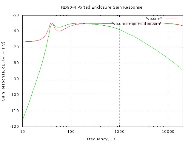
Figure XVI is the ported ND90-4 frequency response of the ported ND90-4 with two Sallen-Key high-pass filters to shift the phase of the ported ND90-4, addressing the issues of group delay.
Figure XVII is the ported ND90-4 phase response of the ported ND90-4 with two Sallen-Key high-pass filters to shift the phase of the ported ND90-4, addressing the issues of group delay.
Figure XVIII is the ported ND90-4 group delay of the ported ND90-4 with two Sallen-Key high-pass filters to shift the phase of the ported ND90-4, addressing the issues of group delay. Note that the high-pass filters are a simplified model of the ported ND90-4 and enclosure. There are limits to the gain that can be used in compensating circuits-specifically, the maximum power that the driver can handle.
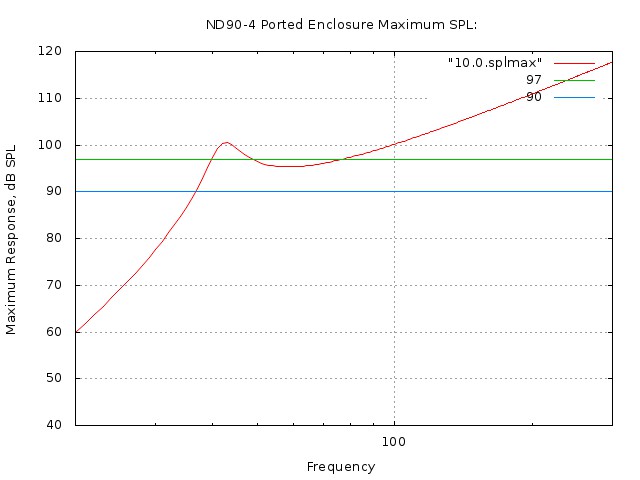
Figure XIX is the maximum output power, at a specific frequency, that the ND90-4 ported design can handle. The Sealed Design
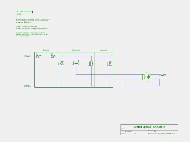
Figure XX, (1600X1200),(3200X2400), is the ND90-4 symbol used for the sealed design. And descending down the hierarchy of the ND90-4 symbol:
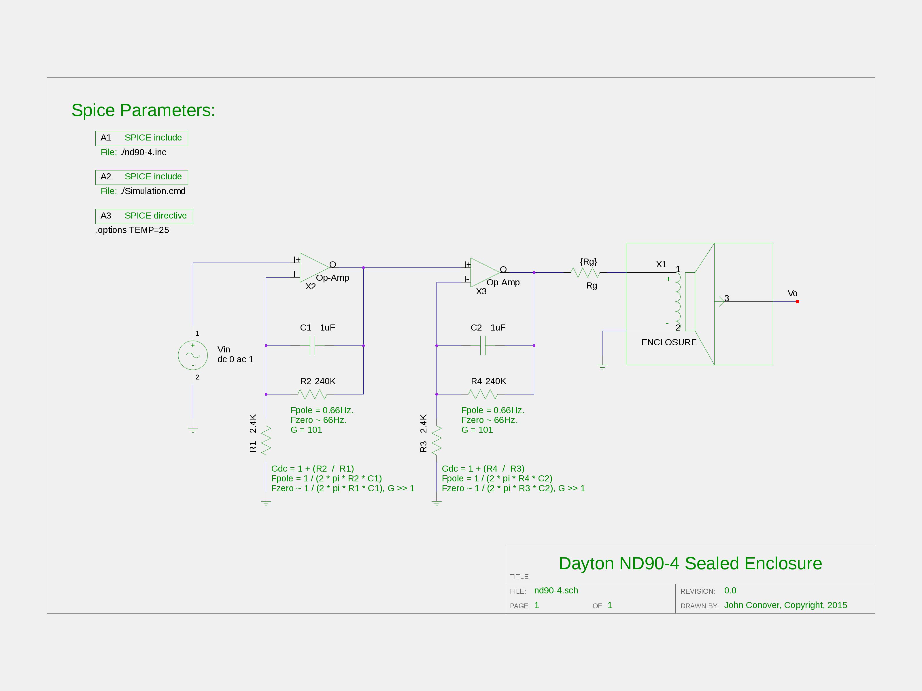
Figure XXI, (1600X1200),(3200X2400), is the schematic of the ND90-4 sealed design using the Thiele/Small parameters.
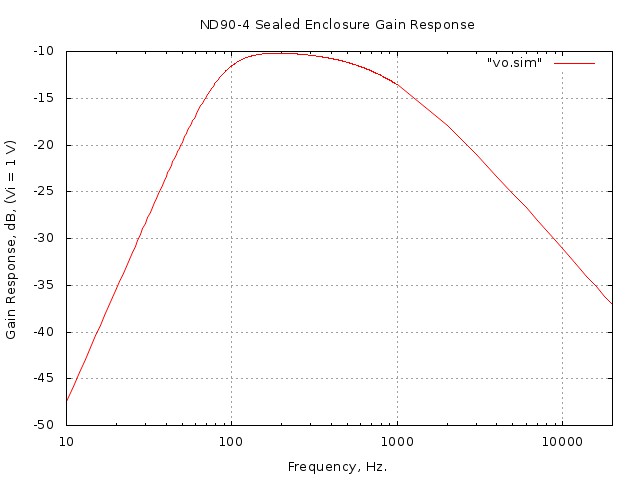
Figure XXII is the frequency response, simulated using Spice, of the sealed design. Note that the ported design has a substantially lower cutoff frequency.
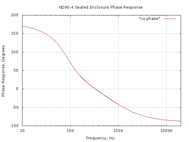
Figure XXIII is the phase response, simulated using Spice, of the sealed design.
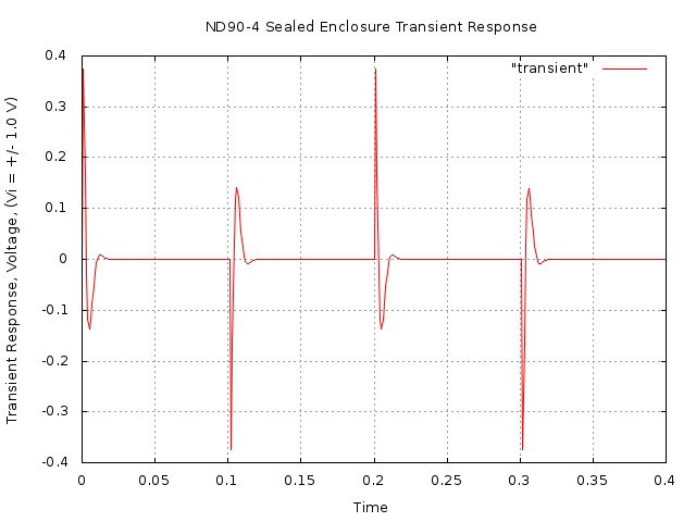
Figure XXIV is the transient response, simulated using Spice, of the sealed design. Note that the ported design has substantially more ringing.
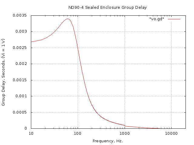
Figure XXV is the group delay, simulated using Spice, of the sealed design. Note the the ported design has substantially more group delay. One of the advantages of using Spice simulations including
the Thiele/Small parameters is the ability to electronically
modify an enclosure's responses.
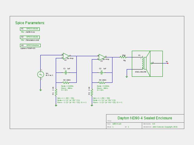
Figure XXVI, (1600X1200),(3200X2400), is the sealed ND90-4 design with a two pole shelving filter addressing the issue of low frequency response.
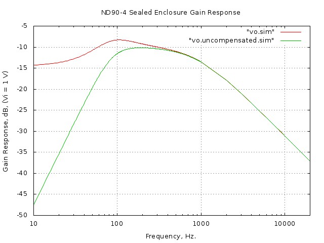
Figure XXVII is the gain response, simulated using Spice, of the sealed design with a two pole shelving filter addressing the issue of low frequency response. Note that the filters, (which have similar characteristics to the tone controls on power amplifiers,) have two zeros at the same frequency as the ND90-4's two low frequency poles-but the frequency response shapes around the zeros and poles are different, creating a bump in the overall frequency response. Note that extending the frequency response down to 40 Hz., (competitive with the ported design,) is not practicable due to power limitations of the ND90-4.
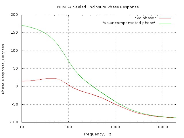
Figure XXVIII is the phase response, simulated using Spice, of the sealed design with a two pole shelving filter addressing the issue of low frequency response. What Was This Project For?It was to investigate the issue of group delay in ported speaker systems. Both the sealed and ported designs are optimal, (or nearly so,) using the same driver in a simple enclosure box, allowing one to place/remove a hand over the port and listen to the difference under different program scenarios. Various simple schemes to improve the ported design's poor group delay, (that's why the components were chosen,) were implemented, also. LicenseA license is hereby granted to reproduce this software for personal, non-commercial use. THIS PROGRAM IS PROVIDED "AS IS". THE AUTHOR PROVIDES NO WARRANTIES WHATSOEVER, EXPRESSED OR IMPLIED, INCLUDING WARRANTIES OF MERCHANTABILITY, TITLE, OR FITNESS FOR ANY PARTICULAR PURPOSE. THE AUTHOR DOES NOT WARRANT THAT USE OF THIS PROGRAM DOES NOT INFRINGE THE INTELLECTUAL PROPERTY RIGHTS OF ANY THIRD PARTY IN ANY COUNTRY. So there. Copyright © 1992-2015, John Conover, All Rights Reserved. Comments and/or problem reports should be addressed to:
|
Home | John | Connie | Publications | Software | Correspondence | NtropiX | NdustriX | NformatiX | NdeX | Thanks
