| john@email.johncon.com |
| http://www.johncon.com/john/ |
|
|
|
||
Studio Speaker |
|||
Home | John | Connie | Publications | Software | Correspondence | NtropiX | NdustriX | NformatiX | NdeX | Thanks
|
The loudspeaker Thiele/Small parameters can be used with the Spice analog electronic circuit simulator to provide behavioral analysis of loudspeaker enclosures. Of particular interest is the frequency response, phase response, group-delay, and transient response of loudspeaker enclosures, each of which can be optimized for maximum performance. The objective of the designs outlined here is a studio quality near field loudspeaker monitor suitable for the mixing and mastering environments, (with additional applications to computer workstations, etc.) The designs will include a ported speaker enclosure version and a sealed speaker enclosure, with substantial electronic mediation. As a general overview, the electronic mediation will have provisions for the crossover network, expanding the bandwidth of the speaker drivers, (both higher, and lower, at the expense of power handling capability.) Only two speaker drivers per channel are used, (a single tweeter and woofer; two woofers for the MTM, Midwoofer-tweeter-midwoofer,) and the enclosure volumes are quite small, (about 5.3 liters for the sealed enclosure, 10.5 liters for the ported enclosure.) The sealed enclosure will have a maximally flat low frequency characteristic for maximum low frequency response, and all other electronic frequency contouring will have Bessel characteristics in the sense of no overshoot-this is a requirement since electronic pole-zero cancellation will be used throughout the design to extend the frequency response of the drivers. Or, in general:
Note the extensive use of electronic mediation. Two enclosure designs are used:
Additionally, a bridge design was implemented, and the development aborted based on thermal management vs. reliability and MTBF issues. The ported design has received little additional development due to group-delay related issues, but is still under maintenance. The electronics is the same in all three designs, including design and fabrication of the PC board. (The ported design allows the the low frequency Linkwitz Transform to be omitted with a "green wire," bridge.) The sealed designs will be presented, below. The DesigngEDA Electronic Design Automation tools, particularly, Gschem(1), was used for schematic capture and Spice electronic circuit simulation netlist extraction. Ngspice was used for the Spice circuit simulations. The design work sheets and data bases for the speakers are available in a single tape archive format, (TAR file, using RCS for version control,) from studio-speaker.tar.gz. A brief overview of the tape archive, after installation in the studio-speaker directory:
Next, there are two executable shell scripts:
The simulation can be re-run after execution of each of these scripts for verification. Finally, the command "make conover.pcb" will auto-route the PC board of the electronics using the standard gEDA command protocol for development of PC boards, (there is no vendor resource file in the distribution, which is usually supplied by one of the many PC board vendors.) Design Walk Through
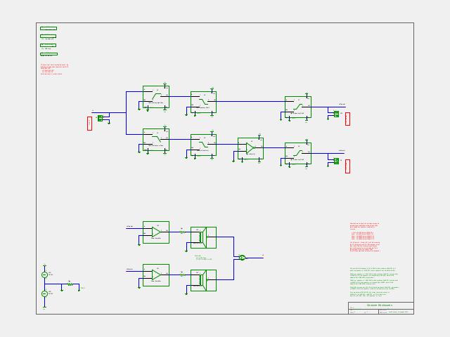
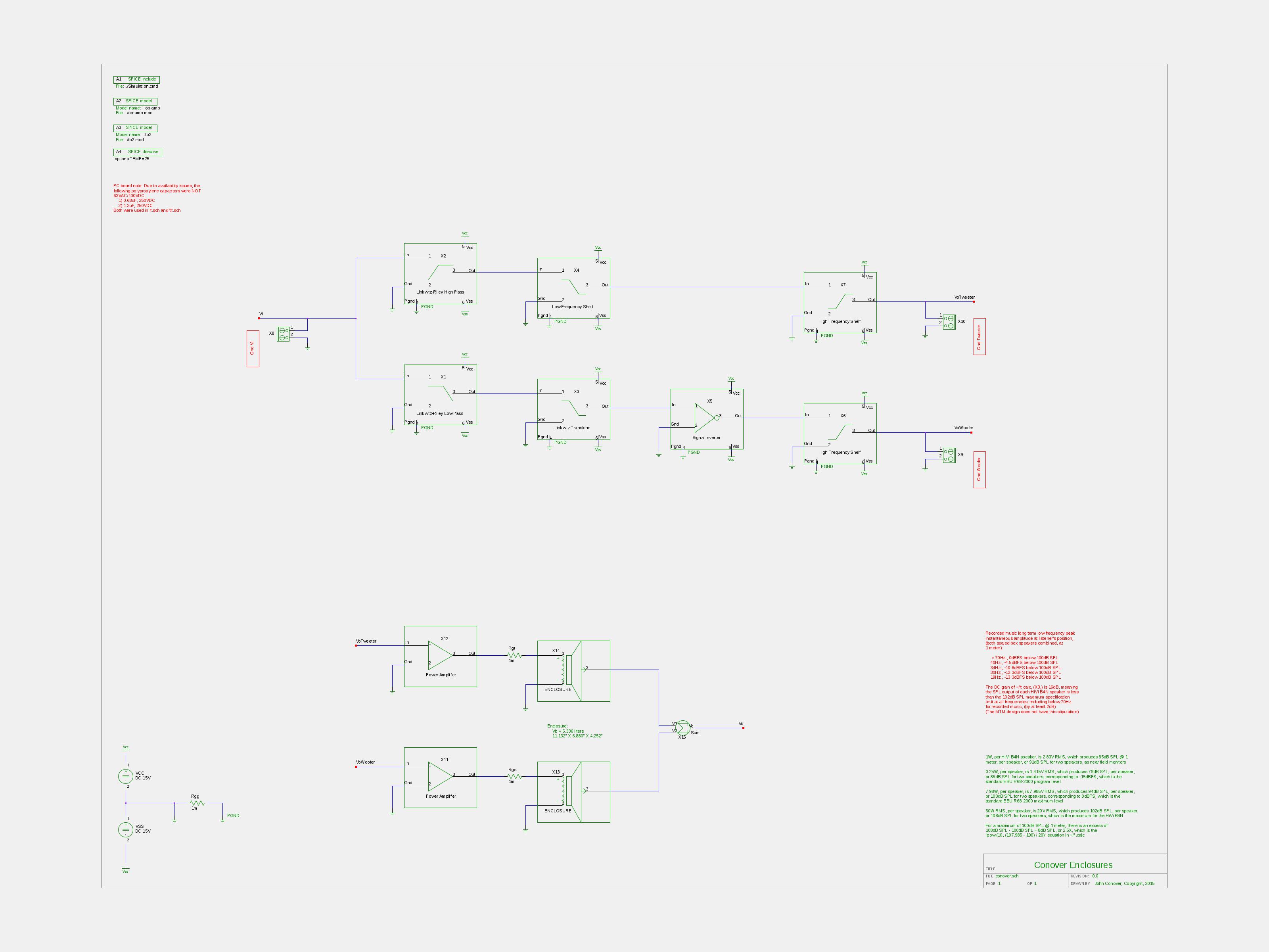
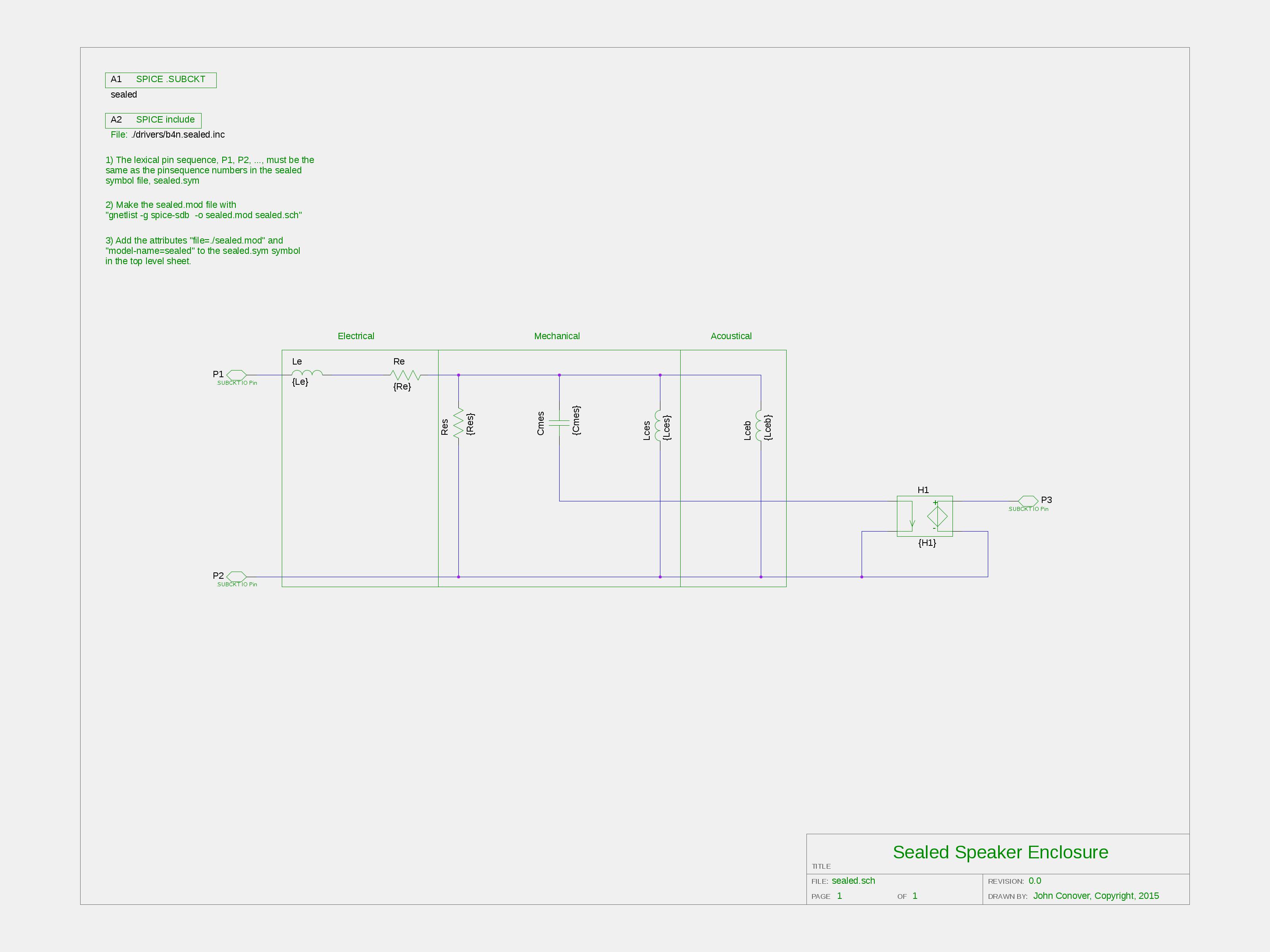
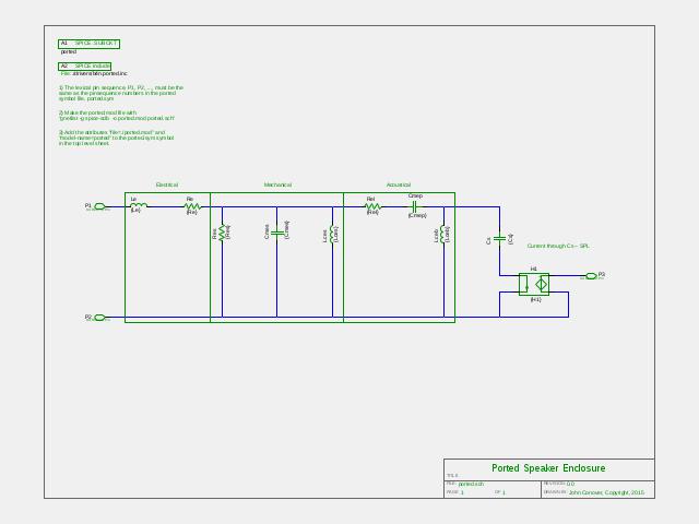
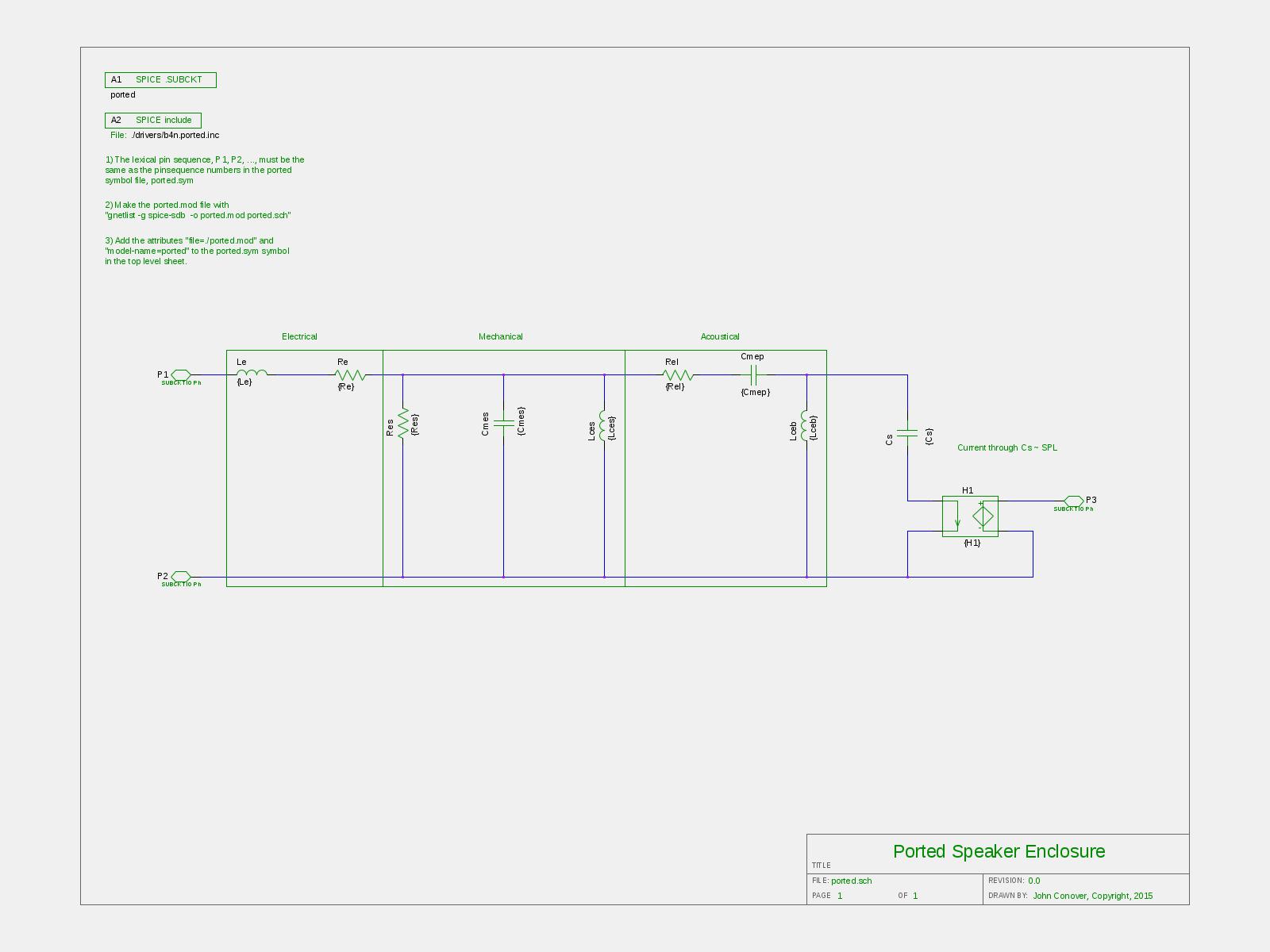
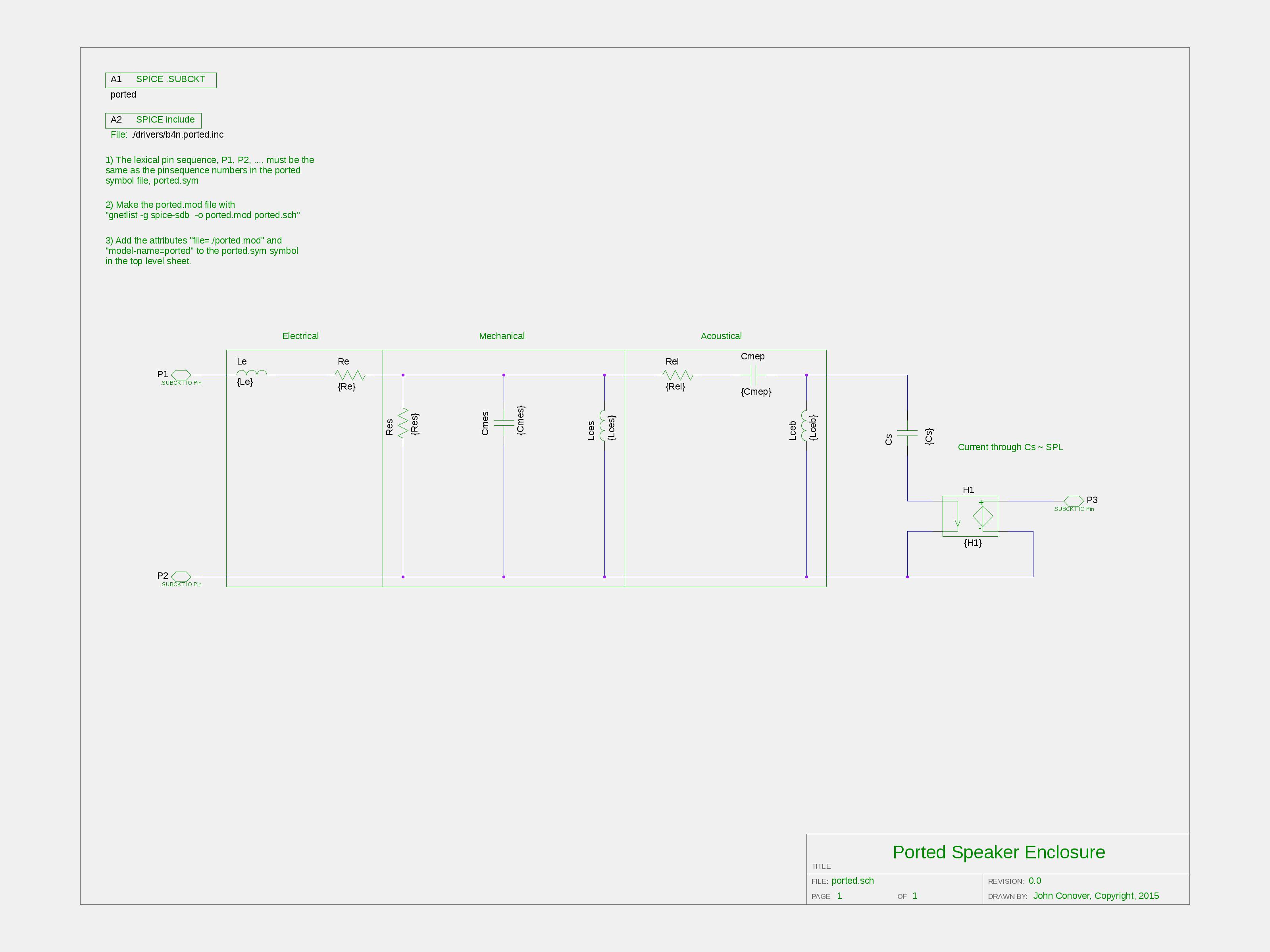
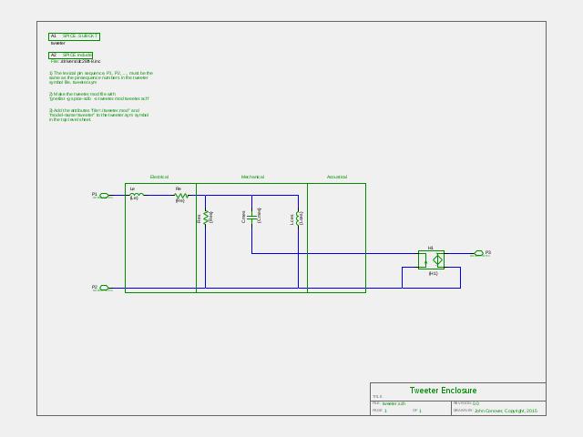
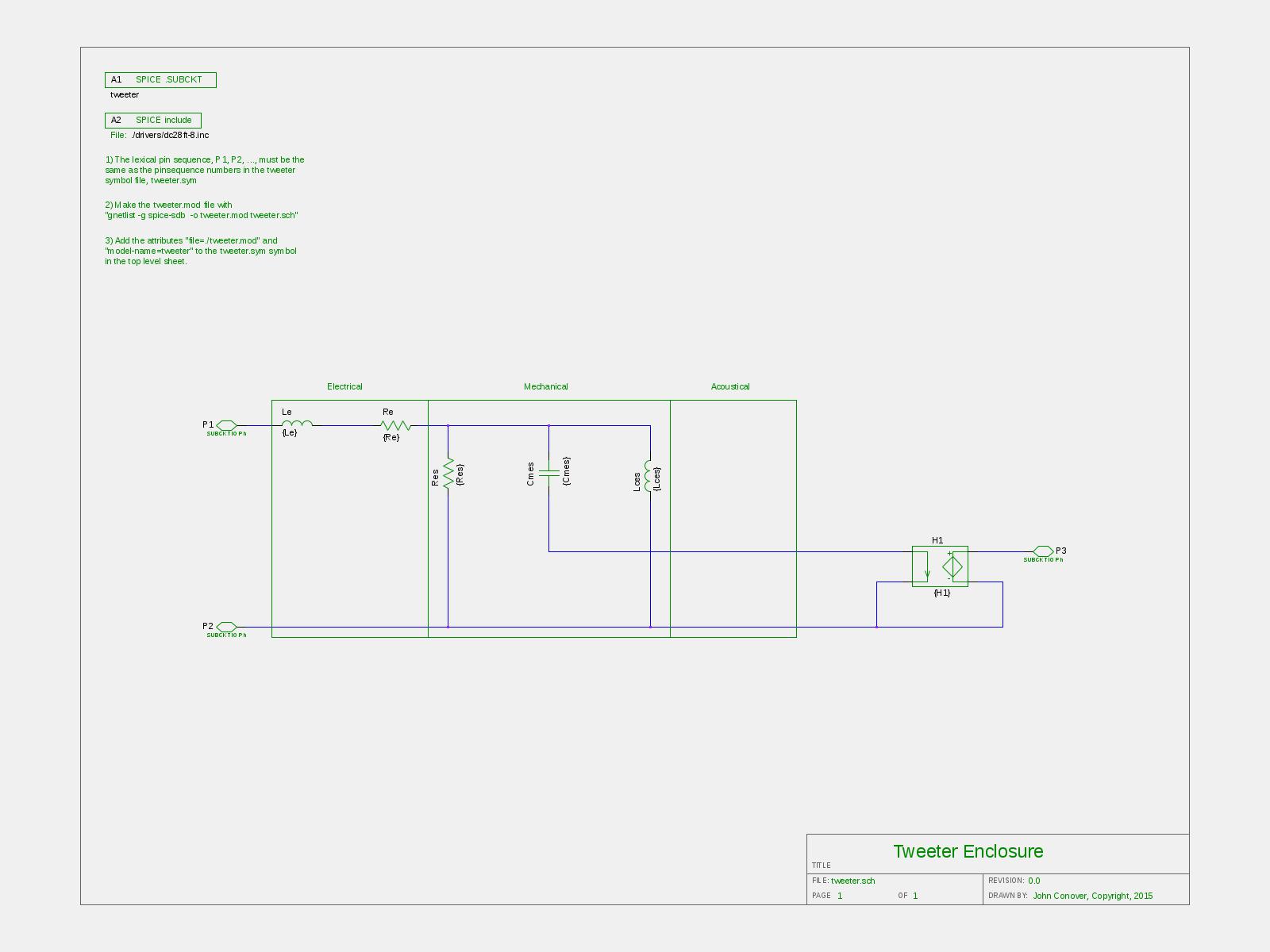
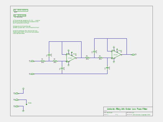
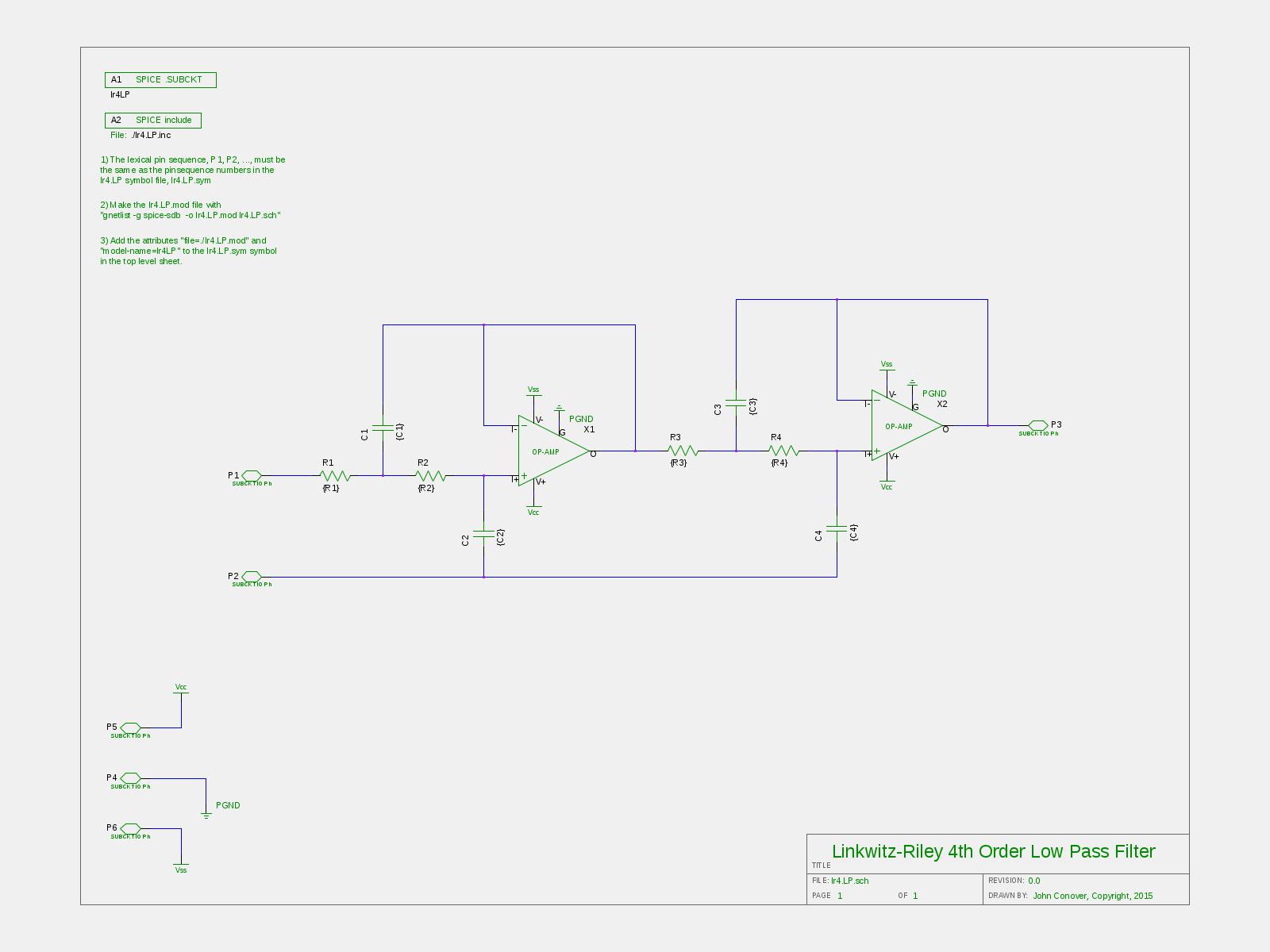
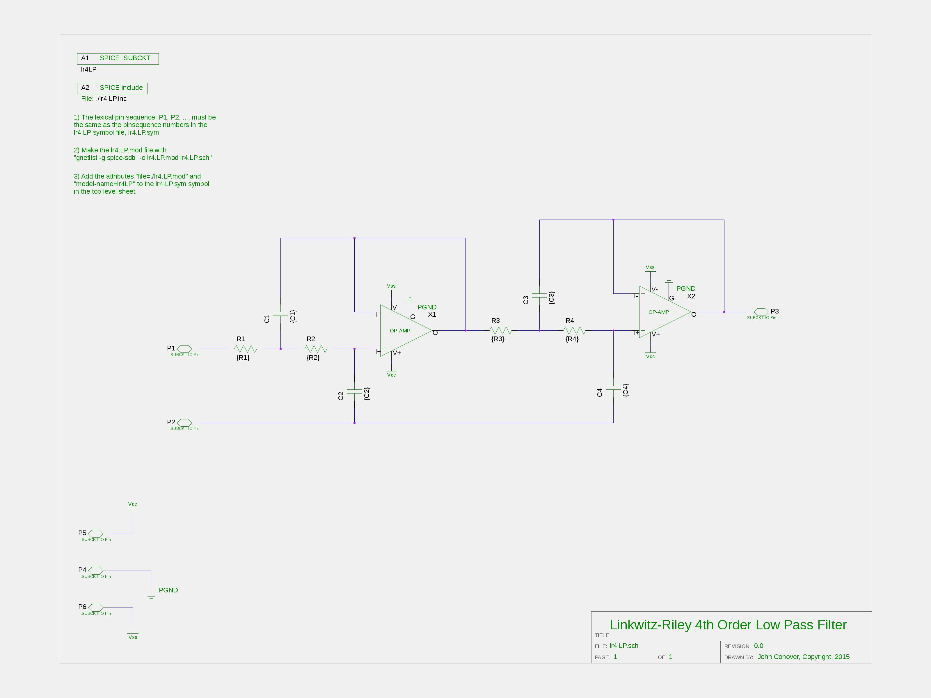
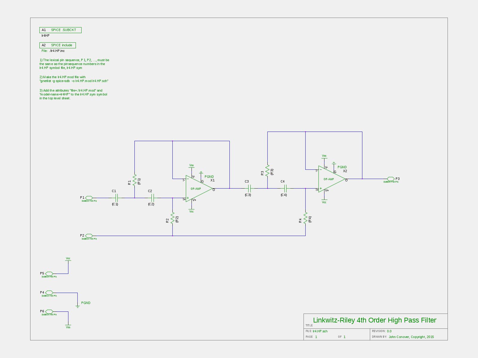
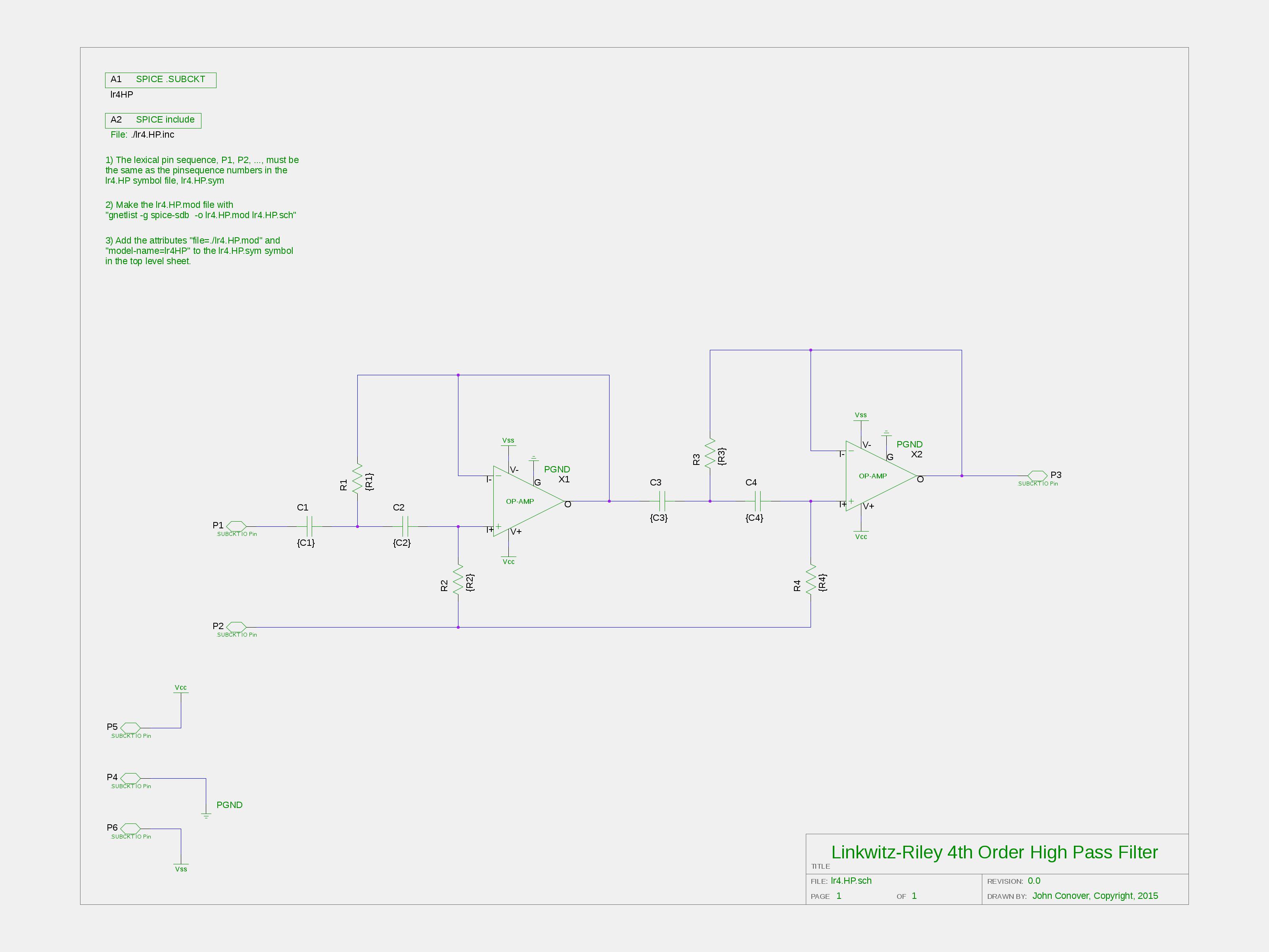
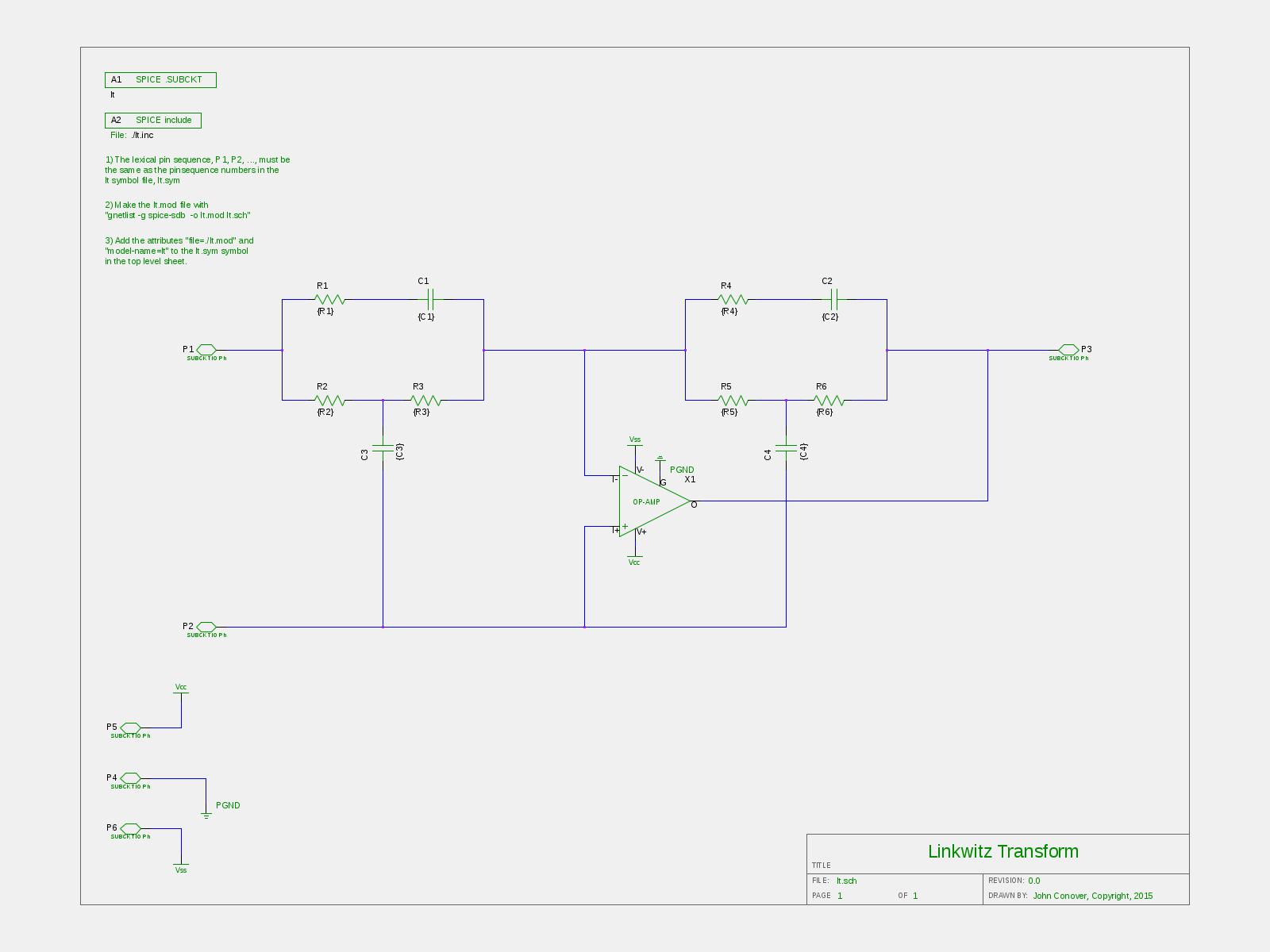
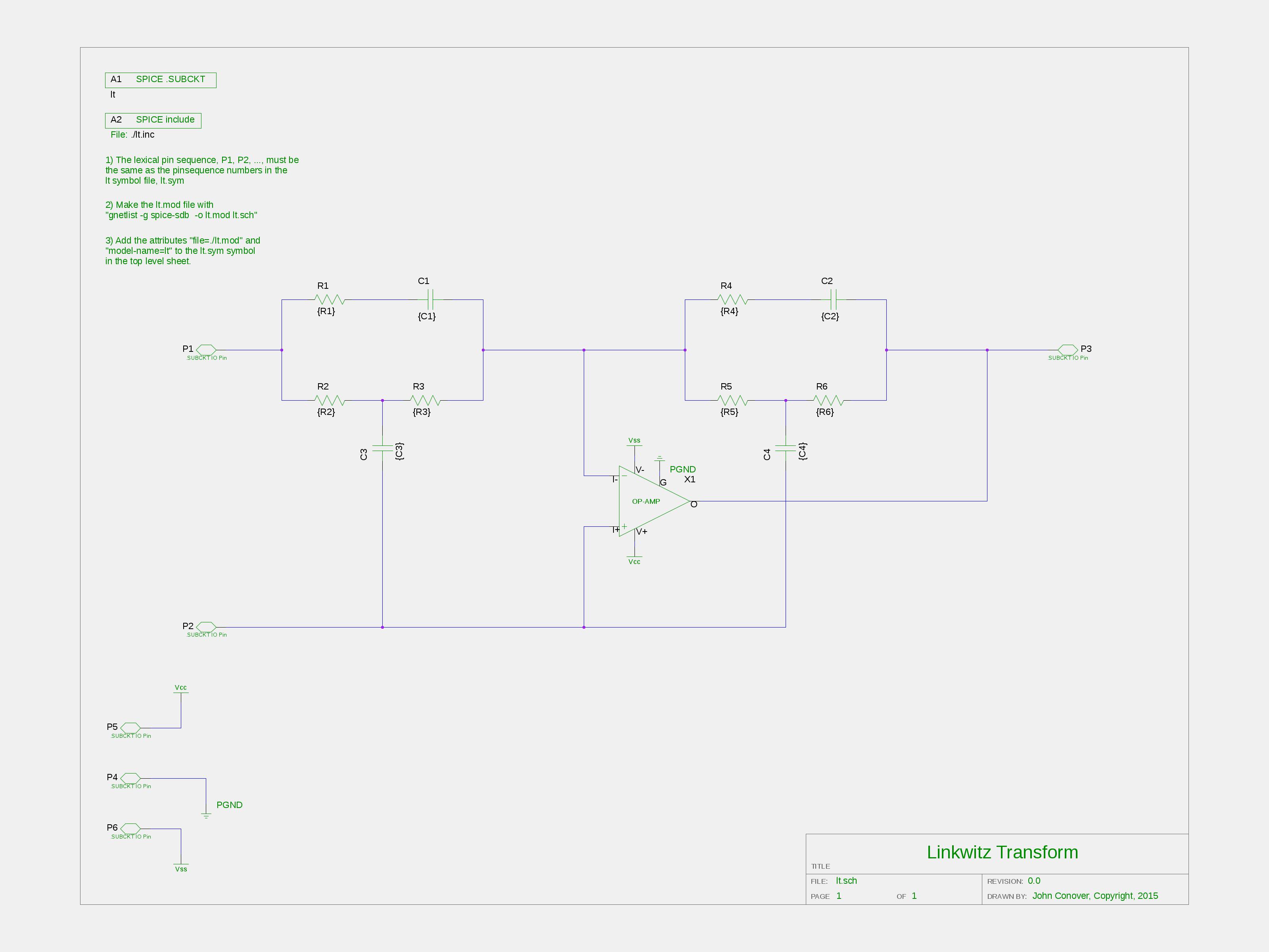
Figure I, (1600X1200),(3200X2400), is the top level schematic of the electronics for the sealed design. At the bottom is the blocks for the Thiele/Small small signal parameters, X13, (1600X1200), (3200X2400), for the sealed enclosure, using the HiVi/Swan B4N driver. (The ported design uses the same electronics, and a different X13, (1600X1200), (3200X2400).) The same tweeter is used in both the sealed and ported designs, X14, (1600X1200), (3200X2400). The incoming signal is divided into a low frequency section, X1, (1600X1200), (3200X2400), and high frequency section, X2, (1600X1200), (3200X2400), using a Linkwitz-Riley 24 dB per octave, (LR4,) crossover. And proceeding through the low frequency signal section, X3,
(1600X1200),
(3200X2400),
is a biquad Linkwitz transform. From sealed-box.calc
with
          HiVi B4N 4" Aluminum Midbass Round Frame, 8 Ohm, $14.91:

            Vb = 5.33564549900267925766 = net box volume, liters
               = 11.132 X 6.880 X 4.252 = golden ratio inside box size, inches
            Fb = 76.14996105085896416634 = box resonant frequency, Hz.
            F3 = 76.14996105085896416634 = box -3 dB frequency, Hz.
            Q  = 0.70710678118654752440 = box quality factor
               @ 0 = maximum peak or dip in speaker system response, db
            L  = 7.41957043973598795245 = minimum longest room dimension, feet
Meaning the B4N and enclosure low frequency response has
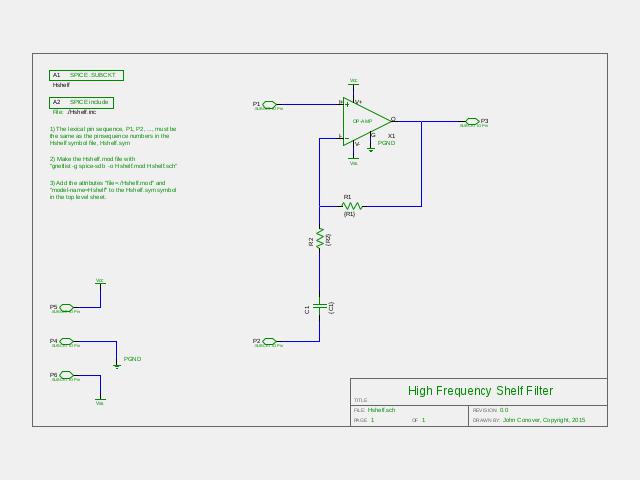
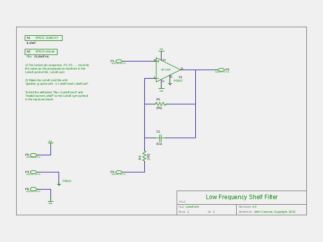
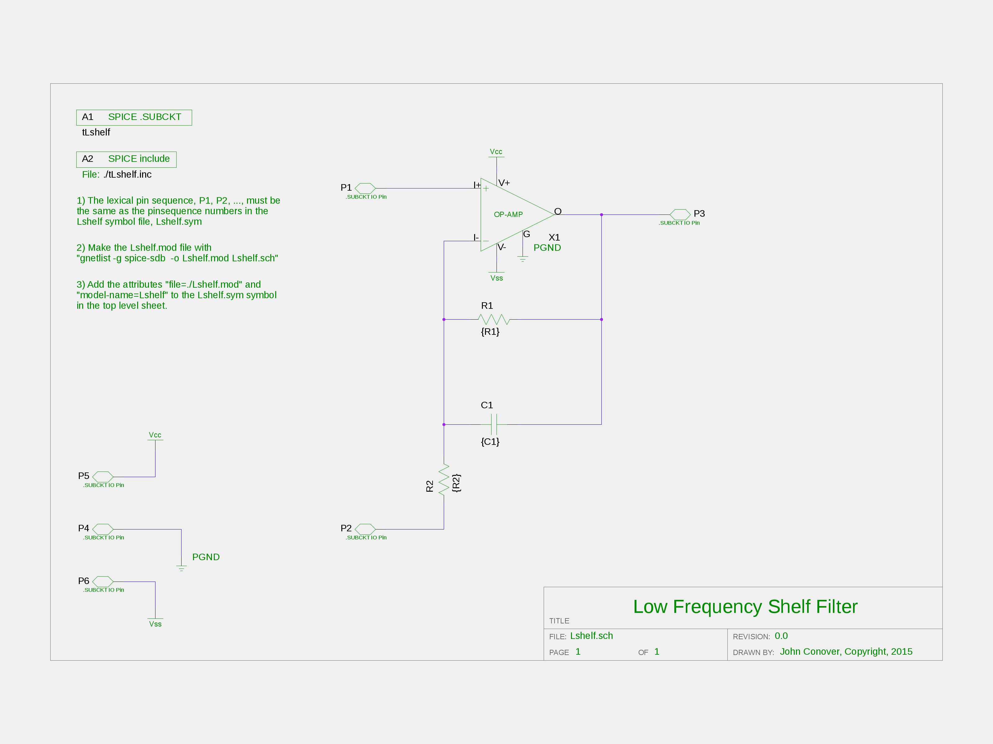
been designed with The biquad Linkwitz transform requires that the signal be inverted, which is done in X5. The next block in the low frequency signal chain is a shelf filter, X6, (1600X1200), (3200X2400), extending the high frequency capability of the B4N. Executing the command "make conover.pk" on the B4N small signal circuit only will present a list of the B4N driver's poles and zeros:
          pole(1) = -1.48954e+04,0.000000e+00
          pole(2) = -3.36598e+02,3.519215e+02
          pole(3) = -3.36598e+02,-3.51922e+02
          pole(4) = 0.000000e+00,0.000000e+00
          zero(1) = 0.000000e+00,0.000000e+00
          zero(2) = 0.000000e+00,0.000000e+00
          zero(3) = 0.000000e+00,0.000000e+00
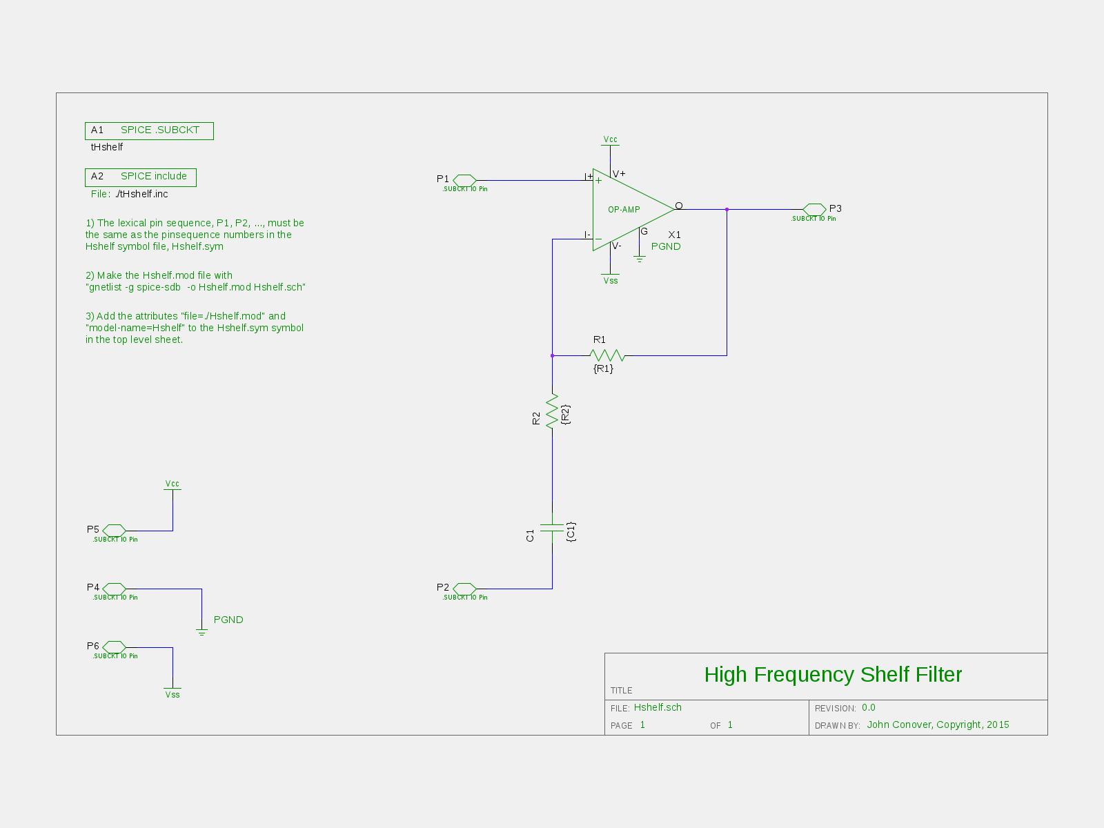
And the high frequency pole, (As an ancillary note, the shelf amplifiers can be manually converted to recursive DSP structures quite expediently. See: tspole(1), for example.) Moving to the high frequency, (top,) signal chain, the aforementioned low frequency pole of the tweeter, (again, from "make conover.pk" on the dc28ft-8 small signal circuit only):
          pole(1) = -5.33928e+04,0.000000e+00
          pole(2) = -1.05629e+04,0.000000e+00
          pole(3) = -1.51725e+03,0.000000e+00
          zero(1) = 0.000000e+00,0.000000e+00
          zero(2) = 0.000000e+00,0.000000e+00
Only the highest frequency pole will be compensated,
The last block in the high frequency signal chain, X7,
(1600X1200),
(3200X2400),
extends the high frequency capability of the tweeter, (using
the above poles and zeros for the tweeter.) The high
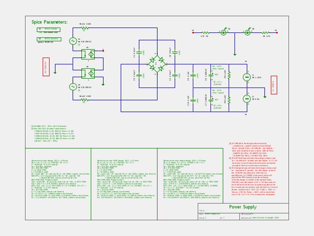
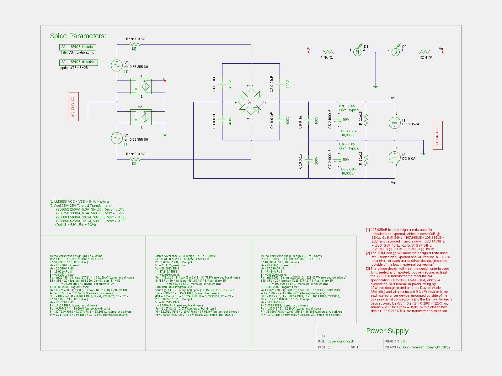
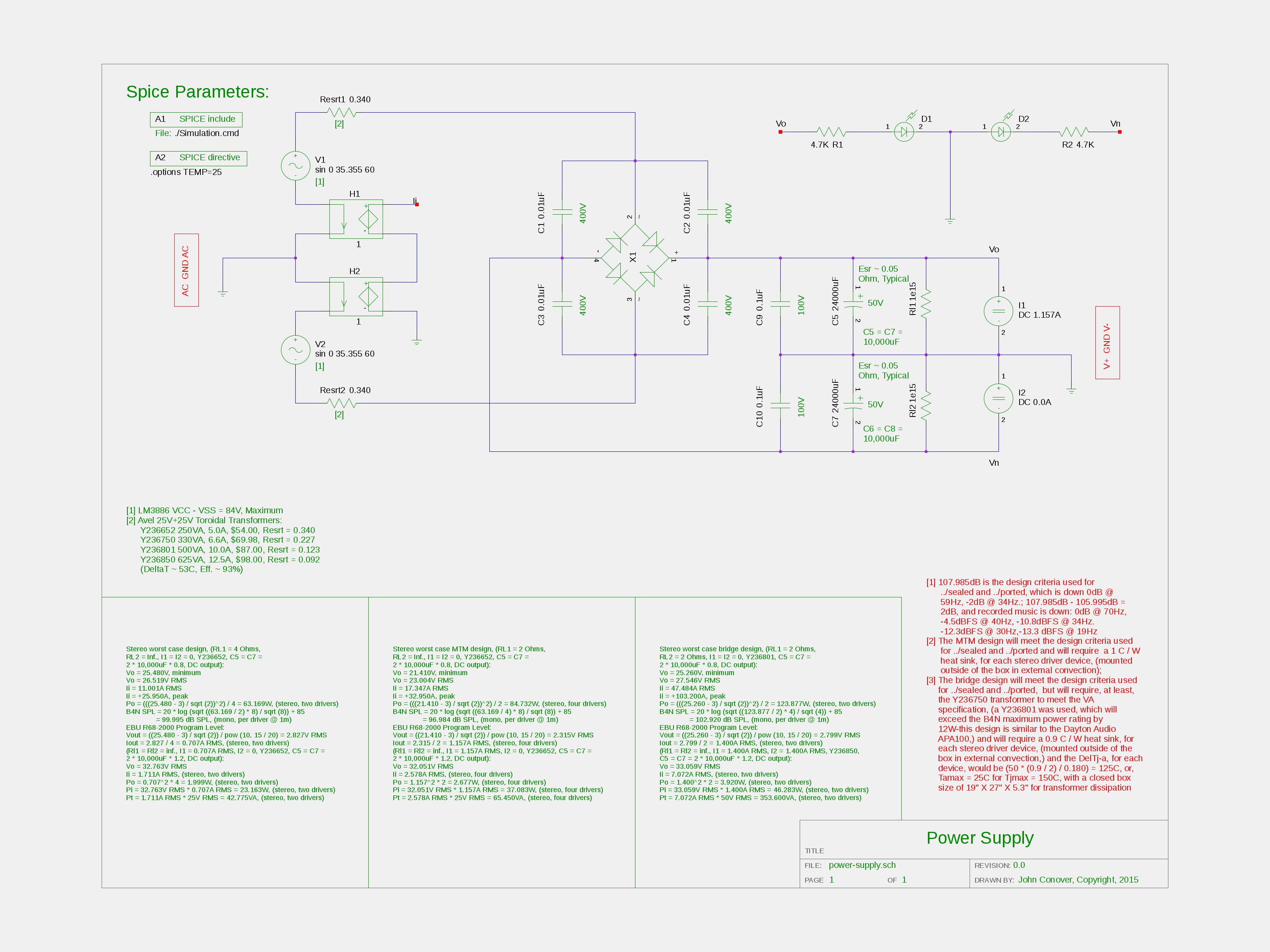
frequency pole is There is one additional schematic, the Power Supply, (1600X1200), (3200X2400). (An attractive alternative would be to use a switching power supply, perhaps using the TL494, similar to what is used in laptop "brick" power supplies-the Lenovo "bricks" can be stacked in series for +/-20V, at about $7 US, each street prices, and adequate for the ported design near field application; the 12V rail on PC power supplies is attractive, also, with +/-30V provided by switching power supplies for automotive audio systems, for about US $30; 24V string LED power supplies, which can be stacked in series for +/-24V is another alternative-but verify the QA/MTBF of the power supplies before purchase.) The Performance
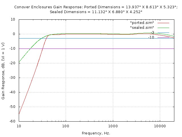
Figure II is the frequency response of the sealed and ported enclosures, including the electronics.
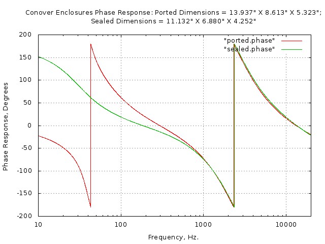
Figure III is the phase response of the sealed and ported enclosures, including the electronics.
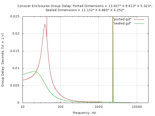
Figure IV is the group delay response of the sealed and ported enclosures, including the electronics. Notice the superiority of the sealed enclosure.
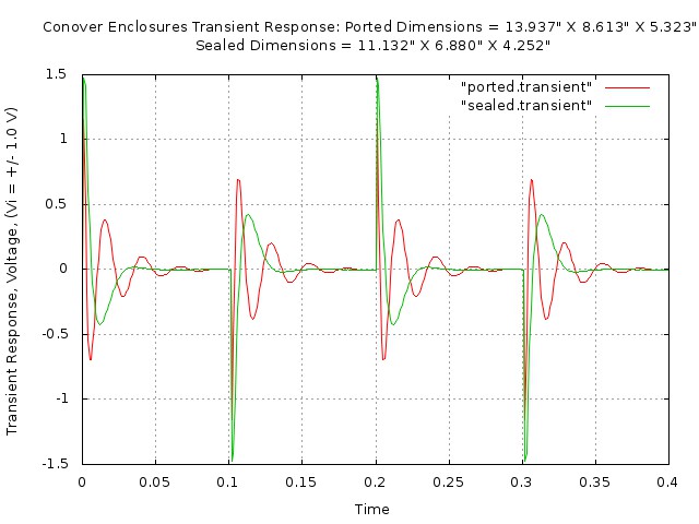
Figure V is the transient response of the sealed and ported enclosures, including the electronics. As a concluding note, professional audio engineers prefer a Bessel low frequency contour, (as opposed to the maximally-flat contour used in these sealed enclosure designs,) but the enclosure size is prohibitive-nearing 20 liters, or more; the actual difference in responses, (the Bessel design is available in the tape archive,) is quite minimal, and a small price to pay for a box volume that is one fourth as large. (Additionally, professional audio engineers tend to focus their attention, and money, on the room environment-in the expensive sense of no parallel walls, etc.-with the relatively inexpensive speaker enclosures built into the wall, or free standing entertainment center.) Short of such an enviroment, near field solutions prevail in the professional community. (Although the current trend is an increasing use of headphones, perhaps with crossfeed to reduce spatial distortion, Ref: Spatial Distortion Reduction Headphone Amplifier.) AppendixThe guideline for near field speaker monitors, (and other sound equipment, for that matter,) is EBU R68-2000, (SMPTE RP 155 is quite similar,) which specifies that the program level is -15dBFS, where 0dBFS is the maximum peak level, (or a crest factor of 5.623.) There is a 3 dB "pad", permitted within the specification, and signals larger, (i.e., 103dBFS,) must be hard clipped, (i.e., the peaks "chopped off," at 103dBFS, in the analog signal chain.) The input signal is now defined. Human hearing does not have flat frequency response-it varies with the sound pressure level, (SPL,) as described by the Fletcher-Munson, (among others,) equal-loudness contours. So how does the aforementioned input signal definition apply to sound pressure level? The balance of music, (i.e., the relative intensity of the low frequencies signals-for example produced by the base and percussion instruments-must be in balance-as in equal potential intensity-to the high frequency signal intensities-for example produced by a flute, or cymbal,) is frequency independent, as in "flat frequency response," starting at about 85dB SPL for human hearing. Thus, -15dBFS corresponds to 85dB SPL where 100dBFS is the maximum signal level, which corresponds to a sound pressure level of 100dB SPL. (Conveniently, OSHA 1910.95 is accommodated by this standard.) Almost all digital music is mixed and mastered, using near field loudspeaker monitors, in accordance with this interpretation of the standards. Why is mixing and mastering done on near field loudspeaker monitors? It is because of the Room Acoustics. The signal from the loudspeaker is summed with the reflections from walls, ceilings, floors, etc., creating a non-uniform frequency response at the listener's location. Near field monitors produce less sound pressure, (because the listener is nearer the speakers, for a given SPL,) and the various reflections are less because the reflections have to travel further to the listener's position, creating a more uniform frequency response at the listener's position. (Although the current trend is to mix/master using headphones, which are more sensitive to group delay issues.) A note about MTH, (Minimum Threshold of Hearing,) i.e., the bottom line(s) on the Fletcher-Munson equal-loudness contours. As an example, at 20Hz., humans can not hear sound levels below about 75 dBSPL. What this means is that distortion products, (created by the non-linearities in the woofer speaker,) can be as high as 5.6%, (at full power output,) and can not be heard by humans-i.e. the woofer drivers can run at relatively high power levels, and still produce acceptably accurate sound. However, at 3KHz., the opposite is true, and humans can hear distortion products that are -105dB below maximum power, which is distortion products of 0.00056%! This is why crossovers are placed in the 2KHz. to 4KHz. range, where both speakers are contributing to sound, (i.e., the output power requirement is reduced by a factor of about 2, for both the woofer and tweeter, for the same SPL output.) This frequency range is the most difficult for the electronics, since negative feedback is used to correct amplifier non-linearities, which requires a significant openloop gain at about 3KHz. for distortion reduction-bottom line, it means specifying amplifiers with large gain bandwidth products for amplifiers with dominant pole compensation. At higher frequencies, the human MTH increases, (but not as significantly as at low frequencies,) but non-linear distortion products have less effect, since the products are higher in frequency than humans can hear. (For example, the second order distortion product would be at 25KHz. for a 12.5KHz. full power signal.) LicenseA license is hereby granted to reproduce this software for personal, non-commercial use. THIS PROGRAM IS PROVIDED "AS IS". THE AUTHOR PROVIDES NO WARRANTIES WHATSOEVER, EXPRESSED OR IMPLIED, INCLUDING WARRANTIES OF MERCHANTABILITY, TITLE, OR FITNESS FOR ANY PARTICULAR PURPOSE. THE AUTHOR DOES NOT WARRANT THAT USE OF THIS PROGRAM DOES NOT INFRINGE THE INTELLECTUAL PROPERTY RIGHTS OF ANY THIRD PARTY IN ANY COUNTRY. So there. Copyright © 1992-2015, John Conover, All Rights Reserved. Comments and/or problem reports should be addressed to:
|
Home | John | Connie | Publications | Software | Correspondence | NtropiX | NdustriX | NformatiX | NdeX | Thanks