| john@email.johncon.com |
| http://www.johncon.com/john/ |
|
|
|
||
Spatial Distortion Reduction Headphone Amplifier |
|||
Home | John | Connie | Publications | Software | Correspondence | NtropiX | NdustriX | NformatiX | NdeX | Thanks
|
In 1971, Siegfried Linkwitz published "Improved Headphone Listening" in the December issue of Audio magazine, (a scanned version of the publication is linked from Improved Headphone Listening - Build a stereo-crossfeed circuit). The objective of Linkwitz' article was to reduce distorted spatial reproduction when listening to recorded stereo music with headphones-the "super stereo" effect where the music seems to be coming from inside one's head. To remove the spatial distortion, Linkwitz reasoned that a small portion of a stereo channel's signal should be fed into the other channel-and presented arguments on the frequency contouring of the required crossfeed. There is a recent Addendum on this page that describes software that implements the spatial distortion reduction scheme outlined on this site-it allows a RIFF/WAVE format selection from a music CD to be "digitally re-mastered" for use with headphones. It works especially well with portable high capacity CD/MP3 players. There is a reason why many musicians and sound/recording/mixing engineers prefer headphones to speakers, (particularly with the recent releases of very good RF and IR connected headphones that remove the leash,) except for casual listening. (Note: there is a companion project, Direct Coupled Stereo Headphone Amplifier, that eliminates output coupling capacitors-and their related problems-and uses the surround sound techniques discussed here.) Low frequency non-directional characteristicsAt half wavelengths longer than the spacing spacing between the ears, directional characteristics of speakers are reduced, and the sound waves will diffract around the head; stereo characteristics can not be reproduced, and each ear will hear about the same sound intensity from either speaker. The strategy to make headphones sound like speakers in a spatial environment at low frequencies is to mix both channels, equally, for frequencies below Fl, (e.g., combine low frequencies from each channel in a monophonic fashion.) The wavelength of a sound signal, w, is:
w = v / f
where v is the velocity of sound, which is about 1100 feet per second. The lower limit for directionality, Fl, is:
f = v / w'
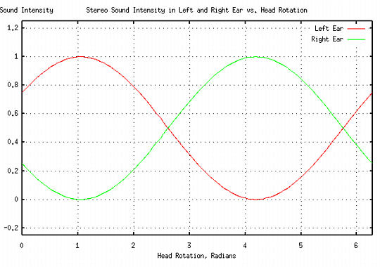
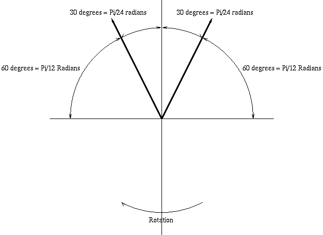
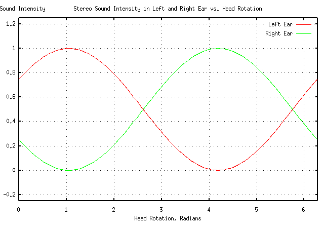
were w' is twice the distance between the ears, or about a foot, or Fl = 1100 Hz. This means that the low frequency listening environment for speakers can be approximated with headphones by crossfeeding about a factor of unity of the opposite channel's signal into the other channel-about doubling the sound intensity below Fl. Although this is an approximation, it is reasonably close to the value used in other designs-Jan Meier used 650 Hz. in An Enhanced-Bass Natural Crossfeed Filter, and Chu Moy used 700 Hz. in An Acoustic Simulator for Headphone Amplifiers. The original Linkwitz paper used 700 Hz., also. High frequency directional characteristicsAssuming an omnidirectional polar response for hearing as an approximation for high frequency directional characteristics in a room with infinite spatial dimensions, (admittedly, a simplistic assumption,) Figure I, (which is available in larger size jpeg, PostScript, PDF, or xfig, formats,) shows a standard for stereo music listening where the speakers are 30 degrees off axis. 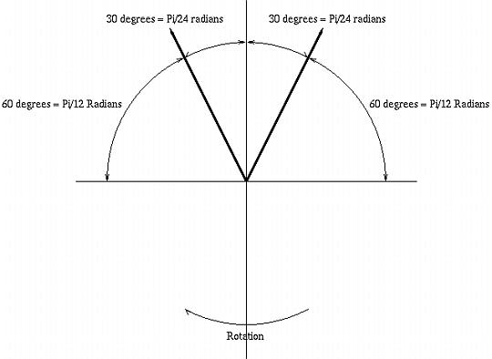 Figure I. Stereo Polar ResponseAs the head is rotated, clockwise, to 30 degrees, the sound intensity in the left ear increases to its maximum, (and the sound intensity in the right ear is zero.) The equations for the sound intensity in the left ear from the left speaker, Ll, and the sound intensity in the left ear from the right speaker, Lr, as the head is rotated r degrees is:
Ll = 0.5 cos (r - 60) + 0.5
and:
Lr = 0.5 cos (r - 240) + 0.5
which is graphed in Figure II, (which is available in
larger size jpeg,
PostScript,
PDF,
or gnuplot,
formats.)
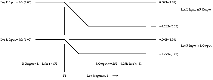
Figure II. Stereo Response vs. Head Rotationor the combined sound in the left ear, at zero degrees rotation, (ie., looking in between the speakers,) would consist of 75% from the left speaker, and 25% from the right speaker. Likewise for the right ear. This means that the high frequency listening environment for speakers can be approximated with headphones by crossfeeding about a factor 1/4 of the opposite channel's signal into the other channel, which is reduced by a factor of 1/4, such that it is still unity sound intensity. Again, this is an approximation, but compares favorably with the original Linkwitz paper which used -3db for the high frequency crossfeed signal ratio. Crossfeed frequency contour characteristicsReiterating the above reasoning, the stereo system speaker environment can be approximated with headphones by:
which is diagrammed in Figure III, (which is available in larger size jpeg, PostScript, PDF, or xfig, formats,) is a Bode plot of the required frequency contour characteristics. 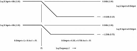 Figure III. Crossfeed Frequency Contour CharacteristicsThe frequency domain is divided into two sections:
Circuit SchematicThe schematic in Figure IV, (which is available in larger size jpeg, PostScript, PDF, or xfig, formats,) is a prototype circuit that implements the required frequency and crossfeed contouring. As a development objective, the low and high frequency contouring and crossfed control elements must not interact-they must be independently adjustable. 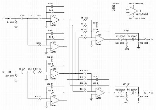 Figure IV. Circuit SchematicDesign walk throughThe circuit description is divided into a low frequency and high frequency analysis-below Fl, and above Fl, where Fl is the single S-plane pole and zero determined by C4-R5 and C3-R4 for the left channel, and C12-R17 and C10-R16 for the right channel. As an overview of the schematic shown in Figure IV, IC1 is the high pass filter, and IC2 the low pass filter, for the left channel; IC4 is the high pass filter, and IC5 the low pass filter, for the left channel. The outputs of these filters are combined in the required ratios by the summing amplifiers IC3 for the left channel, and IC6 for the right channel:
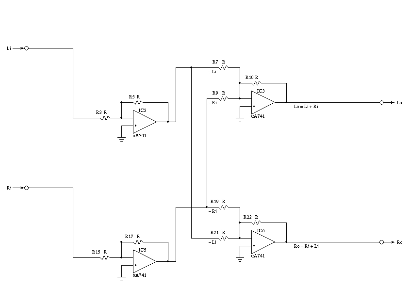
Figure V, (which is available in larger size jpeg, PostScript, PDF, or xfig, formats,) is a low frequency equivalent circuit schematic of Figure IV. 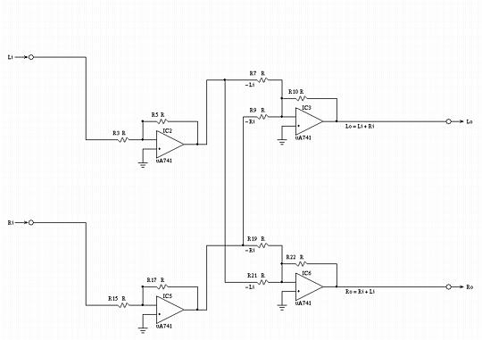 Figure V. Low Frequency Equivalent Circuit SchematicNote that at frequencies below Fl, both the left and right channels are combined to produce monophonic sound, by summing the left and right channel inputs:
Lo = (R5 / R3) (R10 / R7) Li + (R17 / R15) (R10 / R9) Ri
And if:
R5 = R3 = R10 = R7 = R17 = R15 = R9 = R
then:
Lo = Li + Ri
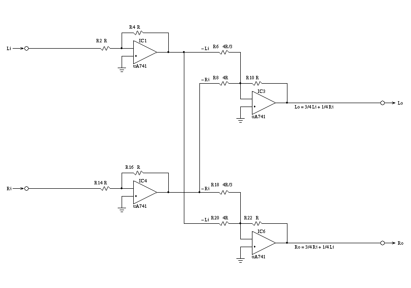
and satisfies the requirement for low frequency contouring. Likewise for the right channel output. If less crossfeed is desired, then R9 and R21 can be increased to be larger than R, (and, could be made variable-but they should track.) If less low frequency gain is desired, R7, R9, R19, and R21 can be increased to be larger than R, (and, all four could be made variable-but R9-R21, and R7-R19 should track.) Figure VI, (which is available in larger size jpeg, PostScript, PDF, or xfig, formats,) is a high frequency equivalent circuit schematic of Figure IV. 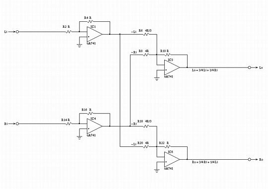 Figure VI. High Frequency Equivalent Circuit SchematicNote that at frequencies above Fl, the left and right input signals are combined to produce "near stereo"; the sound in the left ear phone should consists of 75% of the left channel input signal, and 25% of the right channel input signal:
Lo = (R4 / R2) (R10 / R6) Li + (R16 / R14) (R10 / R8) Ri
And if:
R2 = R4 = R14 = R16 = R10 = R
and:
          R6 = R18 = 4 R / 3
          R8 = R20 = 4 R
then substituting:
          Lo = (R / R) (R / (4 R / 3)) Li + (R / R) (R / 4 R) Ri

             = 3 / 4 Li + 1 / 4 Ri
and satisfies the requirement for high frequency contouring. Likewise for the right channel output. If less crossfeed is desired, then R8 and R20 can be increased to be larger than 4 R, (and, could be made variable-but they should track.) The complex S-Plane poles and zeros for C2-R2, C4-R3, C10 R14, and C12-R15 should all be equal. The zero and pole break points in the Bode plot can be calculated by:
Fl = 1 / 2piRC
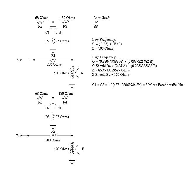
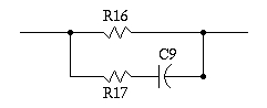
which can be increased, or decreased, (and, could be made variable, but R2-R4, R3-R5, R14-R16, and R15-R17 should track.) Passive ImplementationFigure VII, (which is available in larger size jpeg, PostScript, PDF, or xfig, formats,) is a passive implementation of the circuit shown in Figure IV, and has the same frequency response to within 1 db. The headphone impedance is required to be 100 Ohms, and the circuit output impedance is 100 Ohms at low frequencies, and 85 Ohms at high frequencies.  Figure VII. Passive Implementation of the Schematic in Figure IVThe A and B inputs are assumed to be low impedance sources, (an 8 Ohm output impedance stereo amplifier is adequate,) and the voltage gain to the headphones is 1 / 3. The circuit is relatively straight forward to modify, and the values are ratiometric on the headphone impedance, (i.e., to use 150 Ohm headphones, multiply all values by 1.5, and recalculate the value of C1 and C2, which should be reduced by a factor of 1.5.) Over a relatively large range, the value of R7 and R8 gives linear control of the high frequency crossfeed, (i.e., doubling R7 and R8 doubles the high frequency crossfeed.) The value of C1 and C2 have reasonable linear control of the the low frequency break point, Fl, (i.e., reducing C1 and C2 by a factor of two doubles the low frequency break point, Fl.) AppendixFigure VII, (which is available in larger size jpeg, PostScript, PDF, or xfig, formats,) is a simple RC filter that approximates the contouring functions , of the schematic in Figure IV.  Figure VII. Prototype Filter Circuit SchematicLetting S represent the S-plane complex variable, then by superposition to find the current flowing into the terminals of the filter:
i = v * (1 / R16) + v * (1 / (R17 + (1 / SC9)))
or:
          i / v = 1 / z = ((1 / R16) + (1 / (R17 + (1 / SC9))))

                          (R17 + (1 / SC9)) + R16
                        = --------------------
                          R16 * (R17 + (1 / SC9))

                          R17 + (1 / SC9) + R16
                        = ------------------
                          R16R17 + R16 / SC9
and inverting:
              R16R17 + R16 / SC9
          z = ------------------
              R17 + (1 / SC9) + R16

              SC9R16R17 + R16
            = ---------------
              R17SC9 + 1 + R16SC9
which has an S-plane pole when:
          R17SC9 + 1 + R16SC9 = 0

          - (1 / SC9) = R16 + R17
and an S-plane zero when:
          SC9R16R17 + R16 = 0

          SC9R16R17 = -R16

          - (1 / SC9) = R17
AddendumThe concept can be implemented digitally, too, which is attractive for listening to a collection of MP3s on a portable unit-the CD music selections can be "digitally re-mastered" for use with headphones. Consider listening to a stereo system with speakers. At low frequencies, at half wavelengths longer than the distance between the ears, sound will diffract around the head and there will be no directional characteristics. So, for wavelengths longer than about a foot, (corresponding to a frequency of about 1100 Hz.,) there is no stereo effect. For frequencies below about 1100 Hz., the left and right channels can be simply added together for each headphone channel. Now consider frequencies higher than about 1100 Hz. Those frequencies have directional characteristics; if the sound from the left and right speakers are identical, (i.e., monophonic,) the sound would appear to come from a point source directly in front of the listener-for both speakers and headphones. If the sound from the left and right speakers are not identical, then they would appear to come from point sources to the left and right of a listener with headphones, (which makes the music appear to come from inside the head.) Note that it is a vector addition-identical sound in both channels appears to come from straight ahead in headphones, while different sounds appear to come directly from the left or right. To make sound appear to come from in between those directions, a fraction, the cross feed factor, of one channel must be added to the other, and vice versa. A standard configuration for a stereo system is for the speakers to be located 15 feet apart, and aimed at the listener at an included angle of 60 degrees, which provides an illusion of spatially distributed music. For example, if the listener is looking straight ahead, then the sound level of the right channel would be cos (60) = 0.5 from the right speaker, and cos (120) = -0.5 from the left speaker. If the listener's head turns 15 degrees toward the left speaker, the sound level would raise to cos (45) = 0.707 from the right speaker and cos (105) = -0.269 from the left speaker. Likewise, sound that is balanced in a ratio of 0.707 from the right speaker and -0.269 from the left speaker would appear 15 degrees to the right of the listener, (by reciprocity arguments.) This is the stereo illusion. Most recorded music is mixed according to this model. Looked at from a slightly different perspective, suppose a recording engineer wants the illusion that a sound is coming from a source that is theta degrees to the right of straight ahead. Then mixing the sound level in a ratio of sin(theta) / cos(theta) = tan(theta) between the left and right channels would produce the desired effect. For example, if theta was 15 degrees, then sin(15) = 0.259 and cos(15) = 0.966, or the ratio of right to left channel sound level would be 0.966 / 0.259 = 0.373. (Assuming that the speakers were "spherical radiators.") For headphones to sound like the same stereo illusion-by reciprocity arguments-then the sound should appear to come from two sources separated by +/- 30 degrees, (or 60 and 120 degrees from the axis of the listener's ears.) Recorded music mixed such that a sound level ratio of sin (60) / cos (60) = 1.732 between the left and right speakers would produce sound appearing to come from 30 degrees off axis. Or, a factor of 1 / 1.732 = 0.577 from one channel should be added to the other, and vice versa. So as an approximate model, at frequencies below about 1100 Hz., both the right and left channels are added together for each stereo channel. At frequencies above 1100 Hz., each stereo channel has a cross feed of about a factor of 0.577 = 5 Db. from the other channel added to it-ignoring sound blocking by the head itself. Note that the analysis is in good agreement with the empirical (See: Technical Paper: The Elements of Musical Perception by HeadWize for particulars) literature: E. MacPherson, "A Computer Model of Binaural Localiztion of Stereo Imaging Measuremnt," JAES, September, 1991 claims about a -3 Db. = 0.71, cross feed below 700 Hz. falling to about -10.0 Db. = 0.32 cross feed above 700 Hz., with a 300 microsecond delay, (see: Technical Paper: The Elements of Muscial Perception corresponding to about a quarter of a foot,) in the cross feed between channels. (Which is about -3Db. at all frequencies from the analysis-the above analysis did not include blocking by the head, which apparently is about -3Db.) To produce the single pole low pass filter at 700 Hz., the the sources from the tspole(1) program from the NdustriX, site was used. The single pole low pass filtering of a time series is implemented from the following discrete time equation:
          v      = I * k2 + v  * k1
           n + 1             n
where I is the value of the current input sample in the time series, v are the n'th and n + 1'th value of the output time series, and k1 and k2 are constants determined from the following equations: and
k2 = 1 - k1
where p is a constant that determines the frequency of the pole-a value of unity places the pole at the sample frequency of the time series. For a pole frequency of 700 Hz. the value of p is about 0.016, (p = 700 / 44,100,) and pi is 3.1459 ... The high frequency zero is constructed by multiplying the magnitude of one channel by 0.32, summing it into the other channel, for all frequencies; for frequencies below 700 Hz., the magnitude of one channel is multiplied by 0.71 - 0.32 = 0.39, summing it into the other channel, (e.g., for frequencies below 700 Hz., the left channel has a sound level of L + 0.32R + 0.39R = L + 0.71R,) and above 700 Hz., a factor of 0.32 of one channel is summed into the other, (or the left channel would be L + 0.32R.) The gain is adjusted by multiplying the output by 0.59 to bring the low frequency sound level back near the original. Unfortunately, RIFF/WAVE PCM values are restricted to -32768 to 32767, and since, for frequencies below the pole of 700 Hz., the magnitude has been increased by a factor of 1.71, the gain is reduced by a factor of 0.59. This means, for a mono recording, (i.e., both stereo channels contain the same PCM values,) at frequencies much larger than 700 Hz., the magnitude would be reduced by a factor of 1 + 0.32 / 1.71 = 0.77, or about 2 Db., (voltage or sound pressure, i.e., 20 times log base 10 the ratio.) The delay in the cross feed can be altered using the -d option to the tsheadphone(1) program. The delay equivalent to 0.25 feet, would be about 300 microseconds. The delay is implemented with a ring buffer, each "bucket" representing 1 /44.1 KHz., so 500 microseconds would require 12.3 buckets, or about 13-this delay is inserted in the total cross feed, (including below 700 Hz. and above,) for both channels. The Sources are to the program suite, tsriff(1), tsunriff(1), and, tsheadphone(1). The tsheadphone(1) is the program that implements the headphone compensation. The tsriff(1) program converts a RIFF/WAVE CD music selection to an ASCII time series that is compatible with the NdustriX site's programs on the Utilities page. The tsunriff(1) program does the exact opposite of tsriff(1)-it takes an ASCII time series and converts it back to a RIFF/WAVE CD selection. The programs can be "piped," for example:
          tsriff -p myfile.wav | \
                    tsheadphone | \
                    tsunriff myfile.wav | \
                    lame -V 0 -m s -h - myfile-headphone.wav
can "digitally re-master" a CD music selection file, myfile.wav, for headphone usage, myfile-headphone.wav, in a single command. The NdustriX site's programs on the Utilities page are also helpful. Odds and Ends:
LicenseA license is hereby granted to reproduce this design for personal, non-commercial use. THIS DESIGN IS PROVIDED "AS IS". THE AUTHOR PROVIDES NO WARRANTIES WHATSOEVER, EXPRESSED OR IMPLIED, INCLUDING WARRANTIES OF MERCHANTABILITY, TITLE, OR FITNESS FOR ANY PARTICULAR PURPOSE. THE AUTHOR DOES NOT WARRANT THAT USE OF THIS DESIGN DOES NOT INFRINGE THE INTELLECTUAL PROPERTY RIGHTS OF ANY THIRD PARTY IN ANY COUNTRY. So there. Copyright © 1992-2012, John Conover, All Rights Reserved. Comments and/or problem reports should be addressed to:
|
Home | John | Connie | Publications | Software | Correspondence | NtropiX | NdustriX | NformatiX | NdeX | Thanks